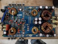
I have a D2 Powerhouse earthquake amplifier? It's a mono lock and it's power supply is down I have no gate drive at the mosfets. I do have a drive signal present at the ic. I can't seem to find it on any of the surrounding components? Anyone have experience repair this type of amplifier,?
Attachments
I'm without any sort of qualification, but find testing 11&14 for voltage tells me nothing. It's not meant to be a DC voltage, so finding one just seems to indicate a measurement error.
I say again.. I just learn about the things I need to fix, when I find the need. I test for frequency though. I would like to see 10s or hundreds of Khz. A sure sign it's trying to operate the fets. Amplitude is obviously important, but I use the AC scale for that. If I found the chip to be giving out DC, I would think it broke. Especially if both pins were DC and nicely balanced. Where is the AC in that?
It's rare that I tread on my own laces. Am I wrong?
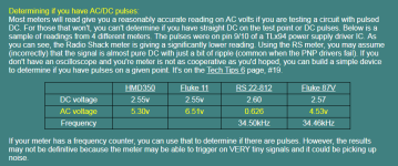
Virtually no one who comes here has a scope so we're left to use what they have, a multimeter. Many multimeters have very limited bandwidth on AC and the readings at 20k+ can vary greatly. Not all meters have a frequency counter.
An example:
Shame they didn't publish the actual figures, along with the ghost ones. To show us how futile it can be to use inadequate test gear. Or how well it works, perhaps.
I have been a little lost at times, so I'm going to rewrite what I have heard so far.
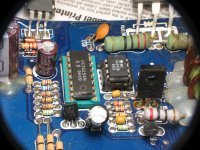
The control chip has funky readings. It's output is directly connected to the 4424 which is a pair of 3 amp fet drivers. The 4424 in turn drives the main semiconductors through the gate driver resistors. Here no signal is found.
If the pin 11&14 voltages were real, and indeed coming from the control chip, then the 4424 should have some sort of output.
I have seen a video cassette loading motor take out it's driver chip, in a manner that took out the cpu. Leaving the cpu outputs hanging around at odd voltages, instead of a two wire flip/flop like logic based output. Panasonic M10 if anyone's finding this familiar.
If armed only with a pink walmart tool kit, I would cut the two traces that carry this 6v between the chips. Then see which chip it's coming from. A pin-out for the 4424 would be very handy, as seen as an isolated device, testing it using the available resources around it, wouldn't be hard. I think we already have tested it and it's broke, but need a pin-out really, and it's supplies checking.
Many amps use 100 ohm gate resistors. Those won't pull the gates of the 3205s down quickly enough unless additional deadtime is programmed into the circuit. 47 ohms is just about as high as you can go with the 3205s with no added deadtime.
For weak circuits driving large numbers of 3205s, the 10 ohm could lead to reliability issues because the instantaneous drive current during the rising and falling edges is higher than with the 47 ohm. The driver IC in this amp will have no problem driving the 3205s with 10 ohm resistors.
For weak circuits driving large numbers of 3205s, the 10 ohm could lead to reliability issues because the instantaneous drive current during the rising and falling edges is higher than with the 47 ohm. The driver IC in this amp will have no problem driving the 3205s with 10 ohm resistors.
- Status
- This old topic is closed. If you want to reopen this topic, contact a moderator using the "Report Post" button.
- Home
- General Interest
- Car Audio
- D2 Powerhouse Earthquake amplifier. Power supply down.