Yes, my meter is auto-ranging. I checked both using ohms. In the direction I get a reading they both start at approximately 1.765m and drop from there(sort of fast at first but quickly slows to a slow continual drop). It is my understanding that they are supposed to have a slow continual drop. In the other direction there is no response on either.
So, I retested the diodes using ohms again. Several times actually. I held the meter on each diode much longer this time to see how far they would drop. Turns out what is actually happening is an up and down fluctuation. Example of one test, when I first applied the leads it read 1.654 it slowly dropped to 1.633 then rose back up to 1.658 then back down again and so forth(it didn't ever get much higher or lower than those numbers). Also noticed they do not always drop first and then go back up, sometimes they go up first and then back down and so forth.
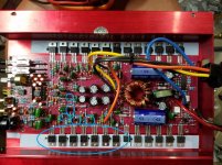
I replaced the 221k resistor with one slightly lower in value and that took care of the problem. That is...only to have a new problem arise. It lost amplification on the right channel. It stills plays music through the right channel but it is not amplifying it. I ohmed all the resistors and they appear to be good. I also pulled and checked (and replaced since I had them) all the transistors I'm aware of that has anything to do with the right channel output(all tested good). I circled them in the attached pic. I'm at a loss as to what to check next next...
Attachments
The 221k was not out of tolerance but resistors over about 100k can cause strange problems.
Are you saying that the output levels are different if you remove the muting transistors?
The overall gain, beyond the op-amp (most of the circuit) is determined by 3 resistors per channel. If I'm not mistaken, one is a 1k between the output wire of the amp and a resistor in one of the resistor modules going to the inverting input of the op-amp. There is another 1k resistor from that inverting input and ground.
None of the other transistors, resistors, nothing determine the overall gain.
Sorry, no, I wasn't saying that the output levels are different if you remove the muting transistors? The pic is an old one from before I was only useing it to show which transistors I pulled and replaced. (ignore that the muting transistors are out in the pic).
What is going on with it is the right channel is only playing music at the volume of the stereo itself. The amp is not amplifying the sound at all on the right channel. The left channel is working fine. The amp worked perfectly for about 5 minutes after changing 221k resistor. I don't believe that has anything to do with the new problem.
What is going on with it is the right channel is only playing music at the volume of the stereo itself. The amp is not amplifying the sound at all on the right channel. The left channel is working fine. The amp worked perfectly for about 5 minutes after changing 221k resistor. I don't believe that has anything to do with the new problem.
Last edited:
Are the muting transistors reading shorted from leg 2-3 (out of the board)?
This is a dead simple circuit. The secondary winding drives the two diodes (connected to the 27.4k and 221k resistors) to negative voltage. The 221k charges the cap and the muting drive voltage slowly goes towards -15v. When the supply stops oscillating, the gate of the 3rd muting transistor is no longer driven and the transistor discharges the capacitor.
In the future, make .030, 0.030 (or .25 >> 0.25...). On fine pitch monitors, the decimal out front can be missed. With it between two numbers, it makes a space that makes it obvious that the decimal is there.
- Status
- This old topic is closed. If you want to reopen this topic, contact a moderator using the "Report Post" button.
- Home
- General Interest
- Car Audio
- Again needing help fixing Orion HCCA 225 Digital Reference