Hi guys,
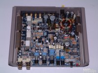
me and my dad are doing a repair on lil' ol' Hifonics Hawk that I got for virtually nothing. We already swapped one transistor, but now we have a voltage drop at the chip marked with red arrow in the attachment. Can somebody tell us what to do next so we can source out the problem? Thanks, cheers!
me and my dad are doing a repair on lil' ol' Hifonics Hawk that I got for virtually nothing. We already swapped one transistor, but now we have a voltage drop at the chip marked with red arrow in the attachment. Can somebody tell us what to do next so we can source out the problem? Thanks, cheers!
Attachments
Sorry, I will try to describe the issue as best as I can. My father is doing the dirty work and I'm trying to find some trick and tips.
Here goes: I got the amp with diagnostics led on power, after which one of the output transistors were changed. Then 27ohm resistor was changed next to the TL594CN, after that swap it finally got +/- 25V for power output. But now operational chip LM358 gets voltage drop, although it was changed and it gets very hot to the touch.
Hope this makes better sense than my first post. Thanks!
Typically, the LM358 (in ZED amps), the LM358 was used in the protection circuit on the primary side of the power supply. Pin 4 was connected to the primary ground. Pin 8 was indirectly powered by the remote input. There was no negative supply voltage for the LM358.
Is your amp different?
Is your amp different?
Mine shouldn't be any different than other Hawk amps, it has the same layout as the amp I posted here.
Correct me if I got this wrong, but aren't positions 4 & 8 on operation chip aimed as power supply for integral transistors?
Sorry if my terminology for amp parts isn't spot on. Cheers!
Correct me if I got this wrong, but aren't positions 4 & 8 on operation chip aimed as power supply for integral transistors?
Sorry if my terminology for amp parts isn't spot on. Cheers!
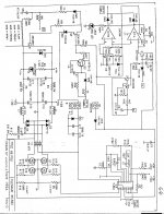
Pins 4 and 8 are the power supply pins but if it's used in the primary side and part of the protection circuit, pin 4 will be connected to ground and pin 8 to a 12v power source. Attached is a diagram from an older ZED amp. I would think your is similar if it's ZED.
I've never seen a hawk model so I don't know if this is a ZED designed amp or not.
I've never seen a hawk model so I don't know if this is a ZED designed amp or not.
Attachments
As far as we know now, oscillator gives signal to LM358 which it evaluates and forwards back to TL594. TL594 functions normally as it seems, but LM358 gets hot in the process even after we replaced it with new part.
On your ZED diagram there is +/- 30V on main power supply after the 'diode brigde' which goes to output transistors and our amp has +/-25V.
On your ZED diagram there is +/- 30V on main power supply after the 'diode brigde' which goes to output transistors and our amp has +/-25V.
Diagram that you got is similar to my amp but not exactly the same.
Mainboard says Hawk XFR. All chip get +/- 15V or +/-25V for output fets.
Only LM358 gets virtually 0V on pin 4 and +0.6V on pin 8, and this chip gets hot under a minute of operation.
My father removed it and finally got 15V behind two resistors 570/5w on output. Maybe he will tryout other LMs in its place to see what will happen next.
For such a small footprint, this amp really gave us major headache...
I don't know if this makes any sense at all, but without LM358 on the board amp works fine. We tried out three different 358s (one that was on the amp and two spares) and every time amp stopped working with them soldered back in place.
There is no DC voltage on pins 1 to 8 with LM358 out, just a short jump when you touch pin 8 and goes back to zero in less than a second...
There is no DC voltage on pins 1 to 8 with LM358 out, just a short jump when you touch pin 8 and goes back to zero in less than a second...
Voltage is always measured with DC mode. My dad has pretty good knowlegde with building (done a few in past three decadees) and repairing home hifi amplifiers. That said, he's still a newbie in the realm of repairing car hifi.
These are the measurement that you asked previously:
With black on pin4 and red on pin8 there is 0V between 4 and 8 without LM358 , when 358 is soldered there is 0,6v between pin4 and 8, 1.6V is measured between 4 and 7 in this situation.
These are the measurement that you asked previously:
With black on pin4 and red on pin8 there is 0V between 4 and 8 without LM358 , when 358 is soldered there is 0,6v between pin4 and 8, 1.6V is measured between 4 and 7 in this situation.
We havent figured out yet what drives pin7, board is very small footprint and it's hard see what feeds the voltage. As soon as we power up amp voltage on pin 8 drops to 1,5 volts.
Resistance from 4 to 8 is around 20k Ohms. ZD1 doesnt seem to be connected between them. Nor does it show any value when you test other pins with Lm358 out...
It would be a lot easier if we had a Hawk amp diagram.
Resistance from 4 to 8 is around 20k Ohms. ZD1 doesnt seem to be connected between them. Nor does it show any value when you test other pins with Lm358 out...
It would be a lot easier if we had a Hawk amp diagram.
- Status
- This old topic is closed. If you want to reopen this topic, contact a moderator using the "Report Post" button.
- Home
- General Interest
- Car Audio
- Hifonics Hawk - Voltage drop question