Xenon 1200.1. The Power supply is good. Due to the protection sensing, it goes into protect so I can't check the output's drive waveforms.
I would prefer to test the drive waves before fitting new output FETs in the amp to ensure I don't blow them. Is there an accepted way to force it to start switching the drive waves?
Thanks!
I would prefer to test the drive waves before fitting new output FETs in the amp to ensure I don't blow them. Is there an accepted way to force it to start switching the drive waves?
Thanks!
Sorry, I misquoted pin 7; that was pin 6. Pin 7 stays at 0V the whole time.
B+ is at 11.5, and drops to 8v for about 0.5s about 1sec after remote power is applied. It then goes to 11.5v and a few seconds later the relay turns on, then goes back off. The B+ V stays at 11.5v afterwards. Current draw is about 3A and drops to 0.1A after protect kicks in.
Remote is the same as B+.
Why is voltage dropping so far?
To disable the protection (you will need to be very careful in case there is a serious problem), be ready to disconnect power from the amp. You can disable the largest group of protection circuits by either lifting one terminal of D9 or by soldering a bridge between pins 3 and 4 of that IC. Do whichever is easier to do and undo.
Attached is an amp that's similar to yours.
Attachments
I'm assuming that you disabled the protection and that's why you now have rail voltage (±90v?).
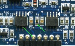
Solder a 10k resistor between the two points shown below. Solder a bridge between pins 2 and 3 of the 21844.
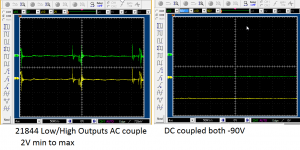
When you drive a 50-100hz signal into the amp, you should have clean audio on the resistor on the output of U3. You should have a square wave swinging ±5v on the output of U4. You should have a 10v square wave swinging from the negative rail up on pin 1 of the 21844.
Solder a 10k resistor between the two points shown below. Solder a bridge between pins 2 and 3 of the 21844.
When you drive a 50-100hz signal into the amp, you should have clean audio on the resistor on the output of U3. You should have a square wave swinging ±5v on the output of U4. You should have a 10v square wave swinging from the negative rail up on pin 1 of the 21844.
Attachments
I did all that and I assume you meant to solder bridge pins 2 and 3 on both of the 21844s?
I don't have any of what you describe as far as waveforms :/
Would the analog audio enter this board? Or does it get converted to digital pulsing in the preamp? I ask because I was trying to find the 100Hz audio wave and it doesn't seem to be present on any of the header pins to this driver board.
I don't have any of what you describe as far as waveforms :/
Would the analog audio enter this board? Or does it get converted to digital pulsing in the preamp? I ask because I was trying to find the 100Hz audio wave and it doesn't seem to be present on any of the header pins to this driver board.
Last edited:
Ok, so the preamp board on this amp is also dead. I'm going to look through the circuit and figure out where it's dead... It doesn't seem to match the preamp in the circuit diagram though, so it will be a bit of tracing out. In the mean-time, I've gotten round to the 2nd amp; so I updated that thread.
Start by confirming that you have supply voltage to all of the op-amps.
Also operate all pots and switches through their entire range with an input signal.while monitoring for audio.
I have a brain the size of a pea and doing two repairs with similar/same amps generally leads to a lot of confusion. That's why I left the other thread alone.
Also operate all pots and switches through their entire range with an input signal.while monitoring for audio.
I have a brain the size of a pea and doing two repairs with similar/same amps generally leads to a lot of confusion. That's why I left the other thread alone.
Start by confirming that you have supply voltage to all of the op-amps.
Also operate all pots and switches through their entire range with an input signal.while monitoring for audio.
I have a brain the size of a pea and doing two repairs with similar/same amps generally leads to a lot of confusion. That's why I left the other thread alone.
Ok thanks I will check tomorrow. And no worries - I have the same problem. I have to keep post-its on the amps to keep them straight

- Status
- This old topic is closed. If you want to reopen this topic, contact a moderator using the "Report Post" button.
- Home
- General Interest
- Car Audio
- Phoenix Gold Xenon 1200.1 Blown outputs