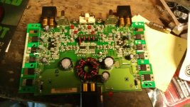
hi all recently joined and i am having a problem with an amp i have had for a while.
the device in suspect is a fosgate punch 55.2 circa 1998
pc-1882-a
the amp had been operating great and sudenly lost power, i had been running it in bridged 2ohm which i know its not rated too and more than likely the reason for failure. when voltage is applied to the remote terminal the led is verry dim the left channel is dead and the right is outputing 1.84v dc. i am new to amp repair and am a little stuck any help in what steps to take for testing would be greatly apericiated
Make sure the channel that is dead is not shorted. If it is you will blow the power supply again. You can clip all the legs of the shorted outputs then safely power the amp.
Likely it needs power supply FET's, gate resistors and power supply drivers. The drivers may have survived, but highly recommended to change.
Once the power supply is up and running, then repair the channel.
Use IRF3205 for power supply with 47 ohm gate resistors. The drivers will be marked 1A and 2A and are near the PWM ic.
Don't have a schematic so not sure board designations on the drivers. Likely Q1 Q2 Q3 Q4
the gate resistors for th power supply fets dont apear burnt and they are labeled 101 and measure 101ohms across the resistor and the gate leg. could i sub irfz40's for the mtp50n06v's?
i have located the drivers is there a way to test them?
also what would i check on the channel for a short the output fets?
i have located the drivers is there a way to test them?
also what would i check on the channel for a short the output fets?
Last edited:
thank you for your help so far! i have the power supply working again,the amp is powering up now yay!! i will order parts for the output section and go from there.
is there maybe something i can do to reduce the likelihood of this happening again,maybe adding heatsinks on the fets or transformer?
is there maybe something i can do to reduce the likelihood of this happening again,maybe adding heatsinks on the fets or transformer?
The best thing you can do is clean all the old thermal compound from the MESHA strips and the heat sink. Apply new thermal compound, I use Dow Corning 340.
This amp has a great heat sink and MESHA board thermal management. I don't think you can do anything extra. Don't run it below the manufacturers recommended impedance.
If you get the devices soldered to the MESHA board flat and securely you should be good. Make sure to have no air voids between device and MESHA board.
You can do it by measuring voltage across the "large blue" source resistors or you can do it by current draw on a amp meter of your power supply.
If you have a power supply with an amp meter turn them clockwise slowly just until the amp draws a little current and then back them off a little until the current draw goes away.
If you don't put your probes from your DMM across a source resistor for each channel and turn them until a slight amount of voltage is present, then back them off until the voltage reads 0.000vdc.
Don't turn them to fast as you risk blowing output devices.
- Status
- This old topic is closed. If you want to reopen this topic, contact a moderator using the "Report Post" button.
- Home
- General Interest
- Car Audio
- fosgate 55.2 wont power up
