Hi folks, I have started another project to RE one of the 3S-tech driver cards. Our fellow member NadaD was in need of a replacement board, and I am currently mostly couch bound and thought that this would be a good way to occupy some time. After almost a month and a half of my trying to find a suitable blown amp to work on, we finally have something and are getting things off the ground.
The goal is to complete and publish schematics, and get a board layout done that we can have made from one of the many inexpensive board houses and have an option to replace severely damaged driver cards without having to find a parts amp.
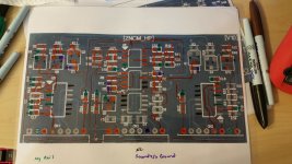
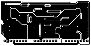
Attached are low resolution scans of the board, linked are the high resolution images hosted on my web page. I also have a completed BOM with all component values. I believe the only part in question is IC U6. I believe it to be a LM393, but am not certain. If anyone can verify, that would be excellent. I will update the BOM with mouser or digikey part numbers in the near future.
Low Resolution front side of board:
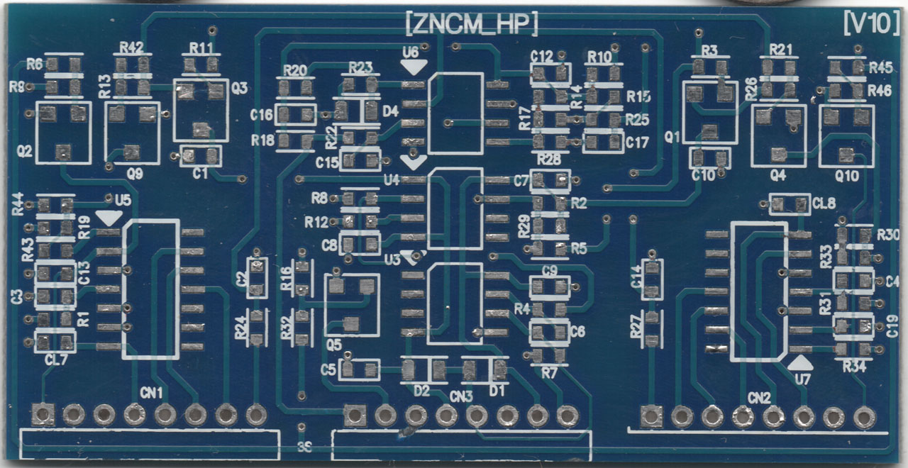
High Resolution front side of board(click)
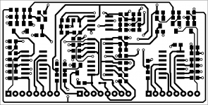
Low Resolution back side of board:
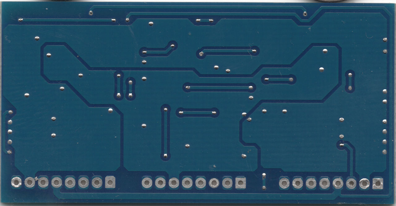
High Resolution back side of board(click)
Spreadsheet BOM in ODS format (click)
Let me know if you spot any errors. I hope to remove the board solder mask today, and start the schematic.
*edit* I just found out that these drivers are not in fact made by 3s as I had assumed. It sounds like they are clones of similar 3s drivers, but are in fact made by Zenon. It doesn't really matter to the grand scheme of things, but it may help someone searching for information on the future.
Thanks!
Jason
The goal is to complete and publish schematics, and get a board layout done that we can have made from one of the many inexpensive board houses and have an option to replace severely damaged driver cards without having to find a parts amp.
Attached are low resolution scans of the board, linked are the high resolution images hosted on my web page. I also have a completed BOM with all component values. I believe the only part in question is IC U6. I believe it to be a LM393, but am not certain. If anyone can verify, that would be excellent. I will update the BOM with mouser or digikey part numbers in the near future.
Low Resolution front side of board:
High Resolution front side of board(click)
Low Resolution back side of board:
High Resolution back side of board(click)
Spreadsheet BOM in ODS format (click)
Let me know if you spot any errors. I hope to remove the board solder mask today, and start the schematic.
*edit* I just found out that these drivers are not in fact made by 3s as I had assumed. It sounds like they are clones of similar 3s drivers, but are in fact made by Zenon. It doesn't really matter to the grand scheme of things, but it may help someone searching for information on the future.
Thanks!
Jason
Attachments
Last edited:
I spent a few hours working on the schematic today. I'm thinking I'm somewhere between 50% and 75% done with a rough schematic. I just took a couple of pictures of my mess to show I was working and to show anyone interested what my workflow is.
I print the scans as full page photos, then line them up back to back. I laminate them together and use wet erase markers to track my progress. Anything color coded on my pictures is stuff I have in the schematic so far. I use a push pin to track vias. This board is not very complex on the back side, but when there are many vias close together the push pin trick works wonders...
If things continue to go well I'll have rough schematics ready tomorrow.
Later,
Jason
Attachments
Thanks Perry, I've tried that before. For me, it's less confusing to do it this way. It's easier for me to keep track of where I'm at if I have the hard copy and can physically mark it up. I realize I could print the overlays, idk, it just doesn't work for me as well.
Thank you for the input though, I never turn down advice, and it's a great tip. Hopefully it will help out some others if they choose to take on some projects like this.
Thanks!
Jason
Thank you for the input though, I never turn down advice, and it's a great tip. Hopefully it will help out some others if they choose to take on some projects like this.
Thanks!
Jason
My oldest daughter is home sick today so I'm not sure how long I'll be able to spend in the shop working on this. I jinxed myself by telling you all I would have a rough schematic today... I'm sorry. I may still get it finished, she is normally OK in the house alone. I just have to e how she is doing.
Thanks for understanding.
J
Thanks for understanding.
J
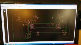
Ok, very rough first draft of the schematic. I will spend the next few days trying to clean it up and make it a bit more readable.
Schematic link
Schematic link
Here is a much more readable version of the rough draft above.
schematic v2 click
I'll start board layout tomorrow, have a busy afternoon today.
Thanks,
Jason
schematic v2 click
I'll start board layout tomorrow, have a busy afternoon today.
Thanks,
Jason
Well, I did have the layout all done and routed. I exported pics, re-saved everything and then went about copying all my data to my several backup locations. After I saved my backups I realized I had been working on one of my backup copies and I actually copied an earlier revision back over the new work! I even copied over many of eagles automated backups because I just back up the whole project folder. I managed to recover one backup from about an hour and a half before the attached screenshot... I'll get back to it again tomorrow and knock it out again.

Attachments
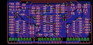
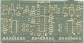
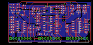
Ok, I finished it again. Lol, I hopefully will avoid doing something stupid like yesterday... Anyhow, attached is a copy of the overall layout as well as images for toner transfer if anyone wants to try to DIY one. Also the front and back layout are linked in a PDF. I will probably send this board to be made as soon as I finish up one more driver card I am working on.
Updated schematic(click)
Toner Transfer layout PDF(click)
Later,
Jason
Updated schematic(click)
Toner Transfer layout PDF(click)
Later,
Jason
Attachments
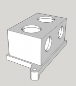
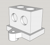
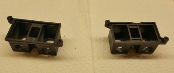
I got bored today, so I knocked this out too. The amp I bought for this driver board came in with one broken power shell. I drew all three of the shells so I can 3d print them. I typically do this any time I get an amp in that has broken plastic. I have a wide variety of stuff already available, so drop me a PM if you need plastic parts...
Attachments
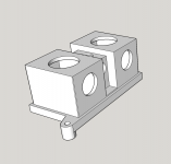
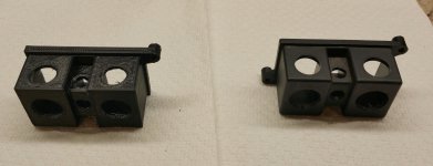
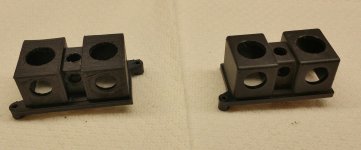
I 3d printed one of the larger ones so you can get an idea how it compares. It's still far too cold out, so I only printed one. Have to keep the shop fairly hot so 3d prints don't fail, and I can't afford to heat it when it's 4° outside...
Attachments
I've not assembled one of these boards yet. Right after I had them made I found that most of the usual sources were back ordered on the irs drivers. My test amps also need significant repairs and I haven't got the loose cash right now to buy the several hundred in parts for them right at the moment. I did start building and testing my "generic Asian clone" driver seen in the pictures above. There is another thread of that name detailing those. They are working well now that I have the current source sorted out.
- Home
- General Interest
- Car Audio
- 3S-tech ZNCM_HP RE project