Yesterday I succeeded extracting an old ATX PSU transformer. I boiled a water can for 10 minutes, turned the heat off and put the transformer inside it for 10 minutes. The ferrite core 2 halves just went off the plastic. I have some questions:
What is the material used to seal the ferrite halves together ?
Should I wind the primary and secondary in opposite directions ?
What is the material used to seal the ferrite halves together ?
Should I wind the primary and secondary in opposite directions ?
Only epoxy will melt, nothing else, don't know where you see any glue...metal said:But why boiled water was able to melt this glue, is it epoxy too that melts under such circumstances
Now I will use your schematic for the car SMPS. What wire gauge did u use and how many wires did u twist together for the primary and secondary as well as # of turns to get 40V on each rail, I do care about ur primary winding as it's most important in this case, then secondary can be calculated.
Another thing on mind, can I use those diodes in the ATX power supply.
Another thing on mind, can I use those diodes in the ATX power supply.
For primary and secondary I used 1mm wire, it is not too small nor too big. You can check on internet how much current it can conduct and || so that current will be higher then one going into converter.metal said:Now I will use your schematic for the car SMPS. What wire gauge did u use and how many wires did u twist together for the primary and secondary as well as # of turns to get 40V on each rail, I do care about ur primary winding as it's most important in this case, then secondary can be calculated.
Another thing on mind, can I use those diodes in the ATX power supply.
Hi
each primary has 6 turns, that is because I have unregulated supply. 4 would be used for regulated, but it is hard to spread them on whole core. Also number of primary wires depend on current, I used hmmm 6-8 wires for each primary? I don't remember, I would need to check. All I know is, it can handle a lot of current
each primary has 6 turns, that is because I have unregulated supply. 4 would be used for regulated, but it is hard to spread them on whole core. Also number of primary wires depend on current, I used hmmm 6-8 wires for each primary? I don't remember, I would need to check. All I know is, it can handle a lot of current
Re: Commentable Thoughts
Iam intrested in ur SMPS.plz mail me ur scematic and other detail(including transformer construction,gauge size of copper wire,stack width of coreetc)advance thanks
Workhorse said:Hi Guys
I have made an amp + smps for my Contessa Classic car.
The smps uses
SG3525 PWM IC
12 X IRFZ44N mosfets
12 X 47ohm Gate resistors
1 X E-I CRGO 4 No. Iron Core Transformerrimary=12-0-12 Multifillar Winding and Secondary 50-0-50 Windings.
one Vero board
2 X 100mFd 25V Caps
2 X 0.1mfd 50V ceramics cap
Couple of other resistors and caps etc.
Frequency is 250Hz
No - Feedback is applied , therefore efficiency is high.
1 X 3.5mFd/250V cap is directly connected to secondary of transformer to suppress spikes.
2 X small heat sinks.
Now the results
No heating on full load only simple warming of sinks
650W power capability
Still alives and is breathing in my car
IF any one interseted mail me.
Iam intrested in ur SMPS.plz mail me ur scematic and other detail(including transformer construction,gauge size of copper wire,stack width of coreetc)advance thanks
Re: Commentable Thoughts
Iam intrested in ur SMPS.plz mail me ur scematic and other detail(including transformer construction,gauge size of copper wire,stack width of coreetc)advance thanks..email me at arun9584@yahoo.com
Workhorse said:Hi Guys
I have made an amp + smps for my Contessa Classic car.
The smps uses
SG3525 PWM IC
12 X IRFZ44N mosfets
12 X 47ohm Gate resistors
1 X E-I CRGO 4 No. Iron Core Transformer
one Vero board
2 X 100mFd 25V Caps
2 X 0.1mfd 50V ceramics cap
Couple of other resistors and caps etc.
Frequency is 250Hz
No - Feedback is applied , therefore efficiency is high.
1 X 3.5mFd/250V cap is directly connected to secondary of transformer to suppress spikes.
2 X small heat sinks.
Now the results
No heating on full load only simple warming of sinks
650W power capability
Still alives and is breathing in my car
IF any one interseted mail me.
Iam intrested in ur SMPS.plz mail me ur scematic and other detail(including transformer construction,gauge size of copper wire,stack width of coreetc)advance thanks..email me at arun9584@yahoo.com
problem with toroid core
hi to all...
i want to help me by luka and pery...
I have finished 2 project of my car amplifier
last project builded with ETD core and current project works with toroid core.
but now I have mistake with yhis core.here is some information of my design:
output voltage at 13.8 volt is +/-47.5 at 6A
core diameter is 44mm outter and 30mm inner
pri winding:5-5(5of1.15mmwires)
sec winding:17-17(3of0.8mmwires)
freq is 33khz
the core and wires gets hot under little load
can this core handle this power that i want?
please help me.
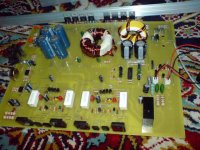
this is my picture of finished 2 channel car amplifier
hi to all...
i want to help me by luka and pery...
I have finished 2 project of my car amplifier
last project builded with ETD core and current project works with toroid core.
but now I have mistake with yhis core.here is some information of my design:
output voltage at 13.8 volt is +/-47.5 at 6A
core diameter is 44mm outter and 30mm inner
pri winding:5-5(5of1.15mmwires)
sec winding:17-17(3of0.8mmwires)
freq is 33khz
the core and wires gets hot under little load
can this core handle this power that i want?
please help me.
this is my picture of finished 2 channel car amplifier
Attachments
Yes like Perry said, core must be the right material, for right application, I have used once some I don't know nothing about, and it got really hot at idle, coz of wrong material. Current draw should be pretty small <<5A.
If your winding is ok, which I assume it is or current draw would be huge now.
After you find this out, we will see where to go from here on
If your winding is ok, which I assume it is or current draw would be huge now.
After you find this out, we will see where to go from here on
- Status
- This old topic is closed. If you want to reopen this topic, contact a moderator using the "Report Post" button.
- Home
- General Interest
- Car Audio
- Making car amplifier SMPS with tl494 + DC Protection