Pardon me if this is out of place here, but I need some help adding regulation to an unregulated supply.
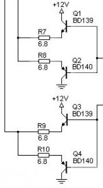
Here is a picture of my attempt at reverse engineering the PCB. This is only part of it, but it's the important parts I think.
Here is a picture of my attempt at reverse engineering the PCB. This is only part of it, but it's the important parts I think.
An externally hosted image should be here but it was not working when we last tested it.
theAnonymous1:
If you understand the way the regulator works, it will be much easier.
You start by setting a reference voltage on one pin of one of the error amps. I generally use error amp A (pins 1 and 2) but either will do the job. Generally, the reference voltage is set to 1/2 of the 5v reg using two series connected resistors (a voltage divider) connected to the 5v reg on one end and ground on the other end. The center point will go to pin 2 of the error amp.
This IC drives harder (increases duty cycle) as the voltage on pin 3 goes lower. For an op-amp (essentially what you have here for the error amps), the output (pin 3) follows the voltage on the positive input (pin 1 here). This means that the voltage on pin 3 will increase (reduce duty cycle) as the voltage on pin 1 goes higher. Having the reference voltage set at 2.5v, the error amp will swing high (towards 5v) when the voltage on the positive input is above the reference and will swing towards ground when the positive input is below the reference.
When you set up the regulator, you will have a second voltage divider connected to the positive input. The resistor values will not be equal like the voltage divider for the reference voltage. The resistor between pin 1 and ground can be the same as the value used for the reference voltage divider. The other resistor (connected between the positive rail and pin 1) will be selected so that pin 1 is pulled up to 2.5v (the reference voltage) when the rail voltage reaches its target voltage.
When the supply is in regulation, the voltage on pins 1 and 2 will be identical. If the supply is driven beyond the point where it can maintain the regulated voltage, the voltage on pin 1 will drop below the reference. The voltage on pin 3 will drop and the duty cycle will go as high as possible.
Thanks Perry. As usual you are a wealth of information and always willing to explain things.
Maybe I need to remove the TL494 so I can get a better view of whats going on. To make things more complicated the error amp of pins 15 and 16 go to a another sub-circuit with an op-amp and some other components.
Maybe I need to remove the TL494 so I can get a better view of whats going on. To make things more complicated the error amp of pins 15 and 16 go to a another sub-circuit with an op-amp and some other components.
You didn't include a full schematic so I'm not sure what you're working with.
If you're using another amp as a guinea pig, you can disconnect the circuit from pin 16 and ground it. That will disable that error amp and may make things less confusing. Don't ground 16 without disconnecting the circuit driving it.
If you remove the 494, the regulated 5v will go away which may make it difficult to determine how the circuit works.
If this is an amp, what make/model is it?
It's the power supply from a BOSS PD4000. It's a decent quality board considering it came from a B***.
I've already changed out the IRFZ44N + 100R gate resistors for HUF75337P3 + 49.9R gate resistors and replaced the 10A diodes with 16A. It runs perfectly but the no load voltage is a little higher than I would like it to be.
http://i27.tinypic.com/2zi30jc.jpg
I've already changed out the IRFZ44N + 100R gate resistors for HUF75337P3 + 49.9R gate resistors and replaced the 10A diodes with 16A. It runs perfectly but the no load voltage is a little higher than I would like it to be.
http://i27.tinypic.com/2zi30jc.jpg
Is this close to what you have? If so, changing the value of the resistors R13P or R12PA would change the regulated voltage. I'd try changing R12PA to ~2k.
http://www.bcae1.com/temp/HMR800-2Schematic.jpg
http://www.bcae1.com/temp/HMR800-2Schematic.jpg
What's different when looking at the connections to pins 1 and 2?
In your diagram, you showed an RC network between pins 2 and 3. That's generally only used when there is regulation. Is it possible that all that's lacking are the two 47k ohm resistors that go to the rails?
What's the voltage on pins 1 and 2 as of now?
In your diagram, you showed an RC network between pins 2 and 3. That's generally only used when there is regulation. Is it possible that all that's lacking are the two 47k ohm resistors that go to the rails?
What's the voltage on pins 1 and 2 as of now?
Pin 1 = 0.944v
Pin 2 = 4.991v
Pin1 and Pin2 look very similar to the sch other than the values of the resistors. There are also no 47k resistors to the rails.
I tried adding a 47k resistor from Pin2 to the positive rail and it didn't change anything. If I change the value of the 5.1k resistor the voltage changes though, even without the 47k resistor to the positive rail.
- Status
- This old topic is closed. If you want to reopen this topic, contact a moderator using the "Report Post" button.
- Home
- General Interest
- Car Audio
- Making car amplifier SMPS with tl494 + DC Protection