which is the best core? fro this ampSMPS
Hi djQUAN,
Thnx for replly.
Actually i want to use in a power amp which build STK4044 as a 300w circuite which came with stk datasheet.
I dont know how many watt its need. may be it required 2-3A 30-50V.
Any way can u tell me which core is best ? EE/toroid?
also suggest me which size core i can used for this EE/toroid?
is EE core is ferrite core?
Regards
Robin
I always use toroids as I already have some of them in stock. ")
I haven't used EE's as I don't know where to get them. basically, toroids are easier to construct (my opinion) but you might need a little practice to get everything right.
EE cores are usually ferrite as they are mostly used for switching supplies. if you're going with toroids, do not use the yellow painted ones as they are powdered iron. (use ones painted grey or green)
how many channels are you going to make with STK4044? is the 300W total or per channel?
you could use a minimun toriod size of around 1.5" diameter and not any smaller.
Has any one here tried this before?
Is there any disadvantage by using such a simple design??
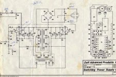
I'll attempt to attach an ancient SMPS schematic from Zapco for their 100WPC amp produced until '91 or so. Somewhere, I also should have their previous 75WPC supply as well. They used no IC's whatsoever, and the supply worked like a charm.
Though the schematic doesn't make note of component values, I do have one of these supplies, and can identify some values if it would be helpful in evaluating a design.
Tim
Attachments

Yes. It is completely possible to make a SMPS for car applications using a linear circuit. Such a circuit is much simpler to design and implement, because it needs no feedback circuitry at all, however, care must be taken to ensure that duty cycles are exactly 50% or else the transformer will overload and bad things will happen.
I'm working on one that I haven't quite had the guts to implement, yet. Baesd on the information that I have, I'm planning on using the CD4047 IC as an oscillator. It have Q ans Q' outputs, which give the required 50% duty cycle using only a single resistor and capacitor as timing elements. This seems simple enough to me that even I couldn't screw it up. From there, I need to build a transformer, and decide what I'm going to use to switch my 12V to the transformer. I have a couple of transformer cores, so it's boiled down to the switching mechanism. I have some NPN transistors which I think I could use, but for more power output, I think I'd need MOSFETs... Or at least to drive multiple transistors in parallel. My first attempt is ging to be for small amounts of power, so a pair of transistors ought to be fine. (I hope)
I'm working on one that I haven't quite had the guts to implement, yet. Baesd on the information that I have, I'm planning on using the CD4047 IC as an oscillator. It have Q ans Q' outputs, which give the required 50% duty cycle using only a single resistor and capacitor as timing elements. This seems simple enough to me that even I couldn't screw it up.
From there, I need to build a transformer, and decide what I'm going to use to switch my 12V to the transformer. I have a couple of transformer cores, so it's boiled down to the switching mechanism. I have some NPN transistors which I think I could use, but for more power output, I think I'd need MOSFETs... Or at least to drive multiple transistors in parallel. My first attempt is ging to be for small amounts of power, so a pair of transistors ought to be fine. (I hope)Can i use EE core transformer in this SMPS
Hi djQUAN ,
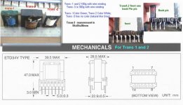
Thnx for replly (post#163). Idid not find any toroids in my city. So i have to looking for "Ferrite EEcore transformer". I found some EE core in a local old spear shop. I think this are EE core (see pic).
Also think this are ETD34V Type transformer(trans1 and 2). caused i found semelar masurement in data sheet. (see my core masurement pic ).
now my question is :
1. is this possible to use this ETD Transformer in this threat SMPS schematics instant of toroids?
2. if possible what size ETD transformer i can use here? may i use my any one of thus? which is the best ETD core trans# 1/2/3? (see pic for size)
3.U suggest me dont buy any yellow label core (coused they are powdered iron) ; i see some ETD transformer are various color label in out side with color tape i.e yellow/green/ white/brown.
My one are green one is white and another one(big one) has no color lebel .
4. is there is any meaning of this color lebel? what is the meaning of each color?
5.how can i determine this is a ferrite core?
6.this are already wire winding and now i can use this winding? how can i masure its pri and secondary winding ratio?
djQUAN for your kind information about STK pls see STK datasheet caused i follow everything from there.
Any one can answer/suggest me pls.
Regards
Robin
Hi djQUAN ,
Thnx for replly (post#163). Idid not find any toroids in my city. So i have to looking for "Ferrite EEcore transformer". I found some EE core in a local old spear shop. I think this are EE core (see pic).
Also think this are ETD34V Type transformer(trans1 and 2). caused i found semelar masurement in data sheet. (see my core masurement pic ).
now my question is :
1. is this possible to use this ETD Transformer in this threat SMPS schematics instant of toroids?
2. if possible what size ETD transformer i can use here? may i use my any one of thus? which is the best ETD core trans# 1/2/3? (see pic for size)
3.U suggest me dont buy any yellow label core (coused they are powdered iron) ; i see some ETD transformer are various color label in out side with color tape i.e yellow/green/ white/brown.
My one are green one is white and another one(big one) has no color lebel .
4. is there is any meaning of this color lebel? what is the meaning of each color?
5.how can i determine this is a ferrite core?
6.this are already wire winding and now i can use this winding? how can i masure its pri and secondary winding ratio?
djQUAN for your kind information about STK pls see STK datasheet caused i follow everything from there.
Any one can answer/suggest me pls.
Regards
Robin
Attachments
I'm working on one that I haven't quite had the guts to implement, yet. Baesd on the information that I have, I'm planning on using the CD4047 IC as an oscillator. It have Q ans Q' outputs, which give the required 50% duty cycle using only a single resistor and capacitor as timing elements.
it maybe simple but I don't recommend it for high power. the IC does not have the "dead time" which both outputs are turned off. using mosfets are necessary for high efficiency at high frequency. also, it doesn't have the "soft start" function which can easily implemented in any PWM controller IC. without soft start, you have the risk of blowing your fuses (depending on tranny size) or having a very high surge current at turn on.
robin,
the EE core transforners that you have are of the right size. BUT you have to remove the windings and make a new one. since the old windings are wired for 120/220V inputs and 12/5V outputs. the tape around EE cores don't mean anything (except for the maker).
how to winding ETD transformer?
Thanks to all for your kind replly.
I want to know how to winding ETD 39 transformer for this SMPS.
1. How AWG i have to use in primary and secondary?
2. how many turns i have to use i primary and secondary?
2pist, can u tell me how to u build ETD transformer? have u use this transformer in this thread SMPS?
any one can suggest me pls.
Regards
Robin
Still waiting...
Hey, djQuan! Still waiting for a schematic. I've got a couple of SG3525 ICs, a couple of TL494s, and a bunch of the 4047s. I have some ferrite cores (finally) and a bunch of un-etched PCB, and some brass bar, so all I need now is a schematic to design from. I'd like to have a few different designs to look at before I embark on the project, as my previous attempts were somewhat less than satisfactory. 
Just looking for options...
Thanks!
Hey, djQuan! Still waiting for a schematic.
I've got a couple of SG3525 ICs, a couple of TL494s, and a bunch of the 4047s. I have some ferrite cores (finally) and a bunch of un-etched PCB, and some brass bar, so all I need now is a schematic to design from. I'd like to have a few different designs to look at before I embark on the project, as my previous attempts were somewhat less than satisfactory. Just looking for options...
Thanks!
you're in luck! I'm in my friend's house, I've just scanned the TL494 controller (hand drawn in my notebook. I was bored during classes ) that I used in my preamp and amp SMPS's.
it's uploaded in my website, I'm gonna make a dedicated page soon. for a preview, here's the address.... (my account does not allow hotlinking so copy and paste the address)
http://djquan.angelcities.com/amp_pics/schem.jpg
edit: the output stage is for a preamp SMPS, for more power, use the drivers and high power mosfets. all diodes are high speed unless noted.
the oscillator does not show component values for the timing resistor and cap. you have to specify one for your requirements. hint: you could try 10k and 1nF as a start.
) that I used in my preamp and amp SMPS's.it's uploaded in my website, I'm gonna make a dedicated page soon. for a preview, here's the address.... (my account does not allow hotlinking so copy and paste the address)
http://djquan.angelcities.com/amp_pics/schem.jpg
edit: the output stage is for a preamp SMPS, for more power, use the drivers and high power mosfets. all diodes are high speed unless noted.
the oscillator does not show component values for the timing resistor and cap. you have to specify one for your requirements. hint: you could try 10k and 1nF as a start.
Hi,
Here's a schematic of complete power supply using TL494. I had tried this and it works perfectly. I'm using EPCOS E32-16-9 N87 grade core and adjust the frequency to 80Khz.The specs from EPCOS says the core can handle 500W Max. at 100Khz.
Check here:
http://www.audiohobbyist.com/caraudio.htm
Hope this help.........
Help me pls
Hi,
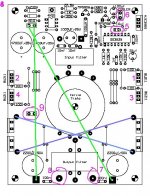
al last i making SMPS as Ristro80's shcematis and PCB diagram (post #5, 6,7). i jsut use ETD39 transformer instand of Triode. and winding was pri-4x4 sec-14x14.
I got some problem when it is running ( i indicated all prob# in the pic):
1. if i use LED, see attachment pic (problem #5) no output volt found. but if i diconnect this LED i can get output volt 55v when input 13.8v
2. i was used a 40w(just connected a 40w buld) load (for testing )in output without LED connection it is working( buld are lighting) find but only BUZ11#1 and #2 are hot littlebit. but BUZ#3,4 are not hot even worm. is this normal. (why not buz 3-4 are wormed?)
3. all time cooler fan are running. is this normal?
how can i wana run cooler only the SMPS are running.
4. where is this SMPS output line?( i think is this #9 )
5.what is the function of point #8 and #9 ??
6. I used extra wire for connection ( Blue and Green colour) this are right way connected? ( confuded caused it was not mantion in PCB Upper /bottom file)
7. there is a remote point near upside 4N35, what is its function. (is this can run /stop SMPS?)
where i connected this point?
8. how can i Test this SMPS with full load with remote function?
any one help me pls
Regards
Bayezid
Hi,
al last i making SMPS as Ristro80's shcematis and PCB diagram (post #5, 6,7). i jsut use ETD39 transformer instand of Triode. and winding was pri-4x4 sec-14x14.
I got some problem when it is running ( i indicated all prob# in the pic):
1. if i use LED, see attachment pic (problem #5) no output volt found. but if i diconnect this LED i can get output volt 55v when input 13.8v
2. i was used a 40w(just connected a 40w buld) load (for testing )in output without LED connection it is working( buld are lighting) find but only BUZ11#1 and #2 are hot littlebit. but BUZ#3,4 are not hot even worm. is this normal. (why not buz 3-4 are wormed?)
3. all time cooler fan are running. is this normal?
how can i wana run cooler only the SMPS are running.
4. where is this SMPS output line?( i think is this #9 )
5.what is the function of point #8 and #9 ??
6. I used extra wire for connection ( Blue and Green colour) this are right way connected? ( confuded caused it was not mantion in PCB Upper /bottom file)
7. there is a remote point near upside 4N35, what is its function. (is this can run /stop SMPS?)
where i connected this point?
8. how can i Test this SMPS with full load with remote function?
any one help me pls
Regards
Bayezid
Attachments
Hello amp_man_1
I am interested. Please send me info at jaugusto@bragatel.pt
or at tempest546@hotmail.com
Thanks
Augusto
I am interested. Please send me info at jaugusto@bragatel.pt
or at tempest546@hotmail.com
Thanks
Augusto
TL494 smps.
Hi all, I have been building car audio for many years. I tried all different controllers and have a fondness for the SG3525. I have made many smps using this chip and have had no failures. There is a TL495 which has pulse by pulse current limiting. recently started with the SG3626 which uses current mode control.
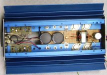
I made one amp using two ETD59 cores for power supply. I wound the primary with copper foil insulated by teflon sheet. The secondary was heavy litz wire taken from an old ultrasonic cleaner supply. The amp ended up with 900 watts RMS per channel into 4 ohms. I have learned a lot the hard way! Litz wire is the only way to go, it gets rid of the "skin effect" and makes the supply more efficient. I recently bought out a transformer winding company's inventory and have a lot of litz wire in my warehouse. I will be offering it for sale as soon as I get it all cataloged.
I am happy to see others in such pursuit of great power. It's a far cry from the self oscillating 15 watt per channel amps I built in the mid seventies. The picture is of an amp I built for myself over ten years ago. The core is an ETD39. Output is 125 watts per channel. I am now working with a new toroid core from Magnetics Inc. On paper, It should be good for over 3kw throughput. The trick will be getting enough wire through the window to handle the current! Best regards, Steve
Hi all, I have been building car audio for many years. I tried all different controllers and have a fondness for the SG3525. I have made many smps using this chip and have had no failures. There is a TL495 which has pulse by pulse current limiting. recently started with the SG3626 which uses current mode control.
I made one amp using two ETD59 cores for power supply. I wound the primary with copper foil insulated by teflon sheet. The secondary was heavy litz wire taken from an old ultrasonic cleaner supply. The amp ended up with 900 watts RMS per channel into 4 ohms. I have learned a lot the hard way! Litz wire is the only way to go, it gets rid of the "skin effect" and makes the supply more efficient. I recently bought out a transformer winding company's inventory and have a lot of litz wire in my warehouse. I will be offering it for sale as soon as I get it all cataloged.
I am happy to see others in such pursuit of great power. It's a far cry from the self oscillating 15 watt per channel amps I built in the mid seventies. The picture is of an amp I built for myself over ten years ago. The core is an ETD39. Output is 125 watts per channel. I am now working with a new toroid core from Magnetics Inc. On paper, It should be good for over 3kw throughput. The trick will be getting enough wire through the window to handle the current! Best regards, Steve
Attachments
- Status
- This old topic is closed. If you want to reopen this topic, contact a moderator using the "Report Post" button.
- Home
- General Interest
- Car Audio
- Making car amplifier SMPS with tl494 + DC Protection