Hello
Hello to every body.You dont need to buy the my car amplifiers you can make it your one.Now reed the text sown on www.valveaudio.com for making car amplifiers 3-4 times on part for dc/dc converter and you will be able to make car amplifier.Plus download car amplifiers pcb protel format from the site + see all the pictures for dc/dc converter and that is!!!!
Now I am finising some car amplifier 1x 200W and I will put pictures + schematic + pcb and thips how to make him
Yours faithfully
Risto Panovski
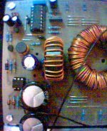
Attachments
Risto, your boards look so good! I just use magic marker then etch. ugly but practical I guess.
I've been trying to retrofit an old amp I built a few years ago but not having much luck. I was using a NE556 timer for the controller but It doesn't have soft start capability. I changed the transformer to a EDT49 core for more power but the initial start up load would blow the fets. I switched to a SG3525 using a Schematic from ESP's web site. the slow sart works well but now It has nasty spikes and runs at 150khz instead of 35khz when I use the 22k timing resistor it calls for. I might have wound the transformer wrong.
I've been trying to retrofit an old amp I built a few years ago but not having much luck. I was using a NE556 timer for the controller but It doesn't have soft start capability. I changed the transformer to a EDT49 core for more power but the initial start up load would blow the fets. I switched to a SG3525 using a Schematic from ESP's web site. the slow sart works well but now It has nasty spikes and runs at 150khz instead of 35khz when I use the 22k timing resistor it calls for. I might have wound the transformer wrong.
Hi Risto,
I used yor smps pcb with same schematic but Rt is reduced at 10k to 3k
and than after smps running at 500mA without anyload(good or not tell
me). So what is the frequency of this smps because i can't it and what
theory of calculation. How ?. I think frequency is not proper so where
is i am wrong. Please answer me.
Thanks for pcb design
My other problame is preamp amplifier whichis i downloaded from valve-
audio's site.Poweroutput is very good but input gain i can't give
properly. I attach the amp's protel pcb file here.Any one can help me
Attachments
Hi All,
I would like to revert back to the subject of this thread. Risto80 were seeking for a SMPS based on TL494.
Here are some schematics I found on the Net. They are from russian sites. TL494 or equivalent seems to be frequently (even nowaday) there.
I don't know a word of russian language but I used automatic translation from BabelFish from Altavista site. Translation is not that perfect but can be understood (or guessed !!)

Hello all.
I published the article you can see in ESP website (Sergio Sanchez).
I am quite happy that now there is a lot of people building their own car SMPS. When I started, I could found only one site(Valveaudio) with useful information, so it took me a lot of experimentation to put it to work.
I will soon retake the design and I would like to know if someone reports problems with flux walking, the so famous problem with push-pull center tapped topologies.
I used the current ITL501 core from Wilco, and also a ETD49. They worked well, but I think that was too big for about 250W. How much power has anyone got from smaller ETD cores, like ETD39, and working reasonably well?
From my experience, I doubt that a car SMPS needs to be regulated, in fact high end home systems have unregulated linear supplies and the fluctuation in the mains are in the same order of magnitude as the car's battery or more. A properly designed amp should be affected (only the max. power, of course) by an unregulated supply.
Using the SMPS in open loop, with 50% duty cycle, allows the use of very small output inductos (chokes). In fact, mine worked very well without them (although I would put at least 5uH chokes if I redesigned it). 50% duty cycle allows for a much more efficient and trouble-free operation of the smps, and also much less ripple.
Just an opinion
Best regards.
Sergio, Your article on ESP is the best one out there. I'm using your SG3525 circuit. ( the one with the pot to control voltage.) The reason I like to regulate is just for the sake of the filter caps. I can use cheaper 35v vs. 50v etc.
Sergio, I ended up using 220k TR the get the KHZ down to about 42. when I used the 20k (I think it was) it runs at 150Khz?
also, have you had any alternator whine in your system? I tried adding an input inductor but It became worse! It feeds back through the the head unit into the rest of the system. Any ideas?
Thanks!
Sergio, Your article on ESP is the best one out there
No, I'm sure it isn't. But I am proud of the fact that I have seen a lot of movement on this issue a few months after I published it, while it was very difficult for me to find anything about car smps. We owe that to the good name of Rod Elliot.
About the frequency, it can be calculated from the datasheet. I really don't remember what it was, I promise to check it as soon as possible.
I did have alternator whine, if I remember well, it dissapeared when I shorted the inputs. But the gain was too high, and when I lowered it to the proper value the whine was almost unaudible. However, it worths the pain investigating its cause, has to be a ground issue.
Best regards

New Project for Car SMPS
Hello
I have read lot of questions from lot of people asking different questions about making Car Amplifiers + SMPS. The answers from those questions can find in the article for making Car Amplifier which is on Valveaudio site.
Now I have another project for Car Amplifier SMPS who can supply Amplifier about 150W, enough for big subwoofer of 300W speaker. The SMPS is very simple and I have made it in Protel99se and printed in PDF format. You can download the zip file. The project I have taste in my car with 100W amplifier for subwoofer- about 250W speaker and work very very good with small hitting in mosfets. You can download the PDF format and the pictures I will put them these days. If there is any questions put them on this site.
Risto Panovski from Macedonia
Attachments
Good job. It may work very well for small powers.
But I have a question: Why do you use non-isolated feedback if the input/output GNDs are separated (as they should)? I have noticed that you simply sample an adjustable portion of the positive output and compare it with Vref/2. But the positive input of the SG3524's error opamp is referenced to input gnd, while the negative input can't be. Please explain this.
Best regards,
Sergio
- Status
- This old topic is closed. If you want to reopen this topic, contact a moderator using the "Report Post" button.
- Home
- General Interest
- Car Audio
- Making car amplifier SMPS with tl494 + DC Protection