Bad or missing drivers can cause FETs to fail.
A1266? Are those the drivers? I hope you didn't order semiconductors from ebay. The BD140 would have been available from a reputable distributor. It looks different but will fit most boards.
Please forgive me (my dumb mistake)... I believe your talking about B649A/D669A in the output section and in between the tombstone resistors - is that correct? I have a transistor tester on order - it should be here tomorrow I'll pull and test them when it arrives.
Attachments
What voltage is on pin 7?
Pin 7 with MM on volts & 12v supply - 0volts.
MM diode test across + & - terminals shows a short.
MM diode shows a short from Pin 7 to the + ternmial but not the - terminal.
It sounds like B+ and ground are reversed. Pin 7 should read 0 ohms to ground. It should also read 0v to ground.
All readings for voltage should be done with the black probe on the main (primary) ground terminal. You should have the meter set to DC voltage.
Also, if you had a short across B+ and ground, you could not have any voltage across those terminals.
All readings for voltage should be done with the black probe on the main (primary) ground terminal. You should have the meter set to DC voltage.
Also, if you had a short across B+ and ground, you could not have any voltage across those terminals.
It sounds like B+ and ground are reversed. Pin 7 should read 0 ohms to ground. It should also read 0v to ground.
All readings for voltage should be done with the black probe on the main (primary) ground terminal. You should have the meter set to DC voltage.
Also, if you had a short across B+ and ground, you could not have any voltage across those terminals.
Hi Perry, Yes thanks - I knew that. But what I'm trying to say and I just re-verified is... With the MM on diode setting pin 7 is shorted on both positive and negative terminals. Also with MM on diode setting the positive and negative terminals also show shorted.
Again when I replace the negative power supply bank of the 3 IRF3205s they fry when I put DC power to the amp even with the small little 12v 3amp power supply I have for testing .
I pulled all 20 of the transistors out of the board and tested all the them - replaced those that were bad.
Any help you can provide sure would be appreciated.
Last edited:
Are all of the PS FETs still out of the board?
If so, check pin 7 to the B+ and ground (nothing else connected to the amp, meter on ohms). Do you read 0 ohms to both from pin 7?
No cooked PS FETs are still in the bank. I'll pull them later this evening as my box with all my soldering gear is at my rental house from installing under cabinet LEDs. I'll reply when I get them pulled. Thanks for all your help Perry it's greatly appreciated.
Hi Perry - I just went ahead and cut the neg side of the PS IRF3205 transistors off the board since the are fried and need to be replaced anyways and I didn't want to wait until later. I did not cut the pos side off the board those are functioning IRF3205 transistors.
Results MM on ohms measuring pin 7 from both pos and neg terminals.
Neg term to pin 7 = .3 ohms
Pos term to pin 7 = 345 ohms
If you need for me to remove the pos side IRF3205 - I can do that later.
Thanks again!
Results MM on ohms measuring pin 7 from both pos and neg terminals.
Neg term to pin 7 = .3 ohms
Pos term to pin 7 = 345 ohms
If you need for me to remove the pos side IRF3205 - I can do that later.
Thanks again!
Last edited:
Hi Perry, thanks here are the results for the TL494 with 12v hooked up.
MM on DCV red lead on pos term black ead on pins.
All pins (including #7) = 12v
MM on DCV red lead on neg term black lead on pins.
All 16 pins = 0V
And I need to add it sparks the + or - wire when I hook up 12v DC to it with the power supply plugged in (without the remote wire attached).
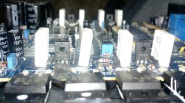
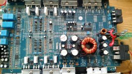
Attached another full board pic of how I just tested it for reference.
MM on DCV red lead on pos term black ead on pins.
All pins (including #7) = 12v
MM on DCV red lead on neg term black lead on pins.
All 16 pins = 0V
And I need to add it sparks the + or - wire when I hook up 12v DC to it with the power supply plugged in (without the remote wire attached).
Attached another full board pic of how I just tested it for reference.
Attachments
Last edited:
Thanks Perry - I'm starting to believe I received a batch of fake IRF3205s or something. I'm not going to mention the supplier here because I can't prove it. I had this amp running but it didn't last long at all before it blew the 3205s again.
I'm going to try mouser this time. Are these the right 3205s? I'm not sure what the PBF at the end means "IRF3205PBF" or if I should be considered about it.
IRF3205PBF Infineon Technologies | Mouser
Thanks again Perry.
I'm going to try mouser this time. Are these the right 3205s? I'm not sure what the PBF at the end means "IRF3205PBF" or if I should be considered about it.
IRF3205PBF Infineon Technologies | Mouser
Thanks again Perry.
Those are OK. PB = Lead F = Free
Did you ever check the drive circuit (if so, which post #).
Hi Perry I have not yet checked the drive circuit. But I learned my lesson on where to put the black MM probe (on the negative ternmial, unless you tell me differently)
") Can you please point me to the drive circuit and where I should be sticking the red MM probe?
Can you please point me to the drive circuit and where I should be sticking the red MM probe? Thanks again.
Those are OK. PB = Lead F = Free
Did you ever check the drive circuit (if so, which post #).
Hi Perry I have not yet checked the drive circuit. But I have learnedness my lesson on where to put the black MM probe (on the negative ternmial, unless you tell me differently)
Can you please point me to the drive circuit and where I should be sticking the red MM probe? Thanks again.
Hi Perry, I have both banks of the PS IRF3205s out of the board.
Here are the results with the Remote wire active:
B+ = 12.32 V
TL494 Pins 9&10 = 4.48
PS negative side FET Bank all gate pads = 4.48 V
PS B+ side FET Bank all gate pads = 4.04 V
Note: PS negative side I replaced all gate resistors with 47 ohm 1/4 watt 1%
Here are the results with the Remote wire active:
B+ = 12.32 V
TL494 Pins 9&10 = 4.48
PS negative side FET Bank all gate pads = 4.48 V
PS B+ side FET Bank all gate pads = 4.04 V
Note: PS negative side I replaced all gate resistors with 47 ohm 1/4 watt 1%
Last edited:
- Status
- This old topic is closed. If you want to reopen this topic, contact a moderator using the "Report Post" button.
- Home
- General Interest
- Car Audio
- Help New Guy (Rockville RXA T1 Car Amp)