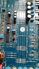
Are DP3 & DP4 zener diodes? They would test as a double diode and not a resistor - correct?
Also pins 9 & 10 on the TL494 (drivers) read 4.48V is this enough to drive the gates of IRF3205 through 47 ohm gate resistors? (See my previous post). I thought I read that the TL494 has a internal 5 volt voltage regulator so it also defective?
Thanks guys.
Also pins 9 & 10 on the TL494 (drivers) read 4.48V is this enough to drive the gates of IRF3205 through 47 ohm gate resistors? (See my previous post). I thought I read that the TL494 has a internal 5 volt voltage regulator so it also defective?
Thanks guys.
Attachments
I think the TL495 data sheet answered my question.
"Internal Regulator provides a stable 5-V reference supply, with 5% tolerance"
5% of 5V is .25V so if I'm understanding the data sheet correctly, pins 9&10 (E1&E2 / drivers) should be between 4.75V to 5.25V. I measure 4.48V on pins 9&10 which is outside of the 5% tolerance. So the TL495 on this board seems to be defective. Am I correct in my thinking here?
TL495 datasheet link ---> https://www.google.com/url?sa=t&sou...FjAHegQIDxAB&usg=AOvVaw20VGoMbyMbZIDaGYKDiWJf
Last edited:
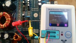
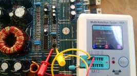
Also you'll see here that DP3 (zener diode) is testing as a 132.9 ohm resistor. But DP4 tests as a double diode.
I believe since the DP3 zener diode is also defective and could be the reason why the bank of IRF3205s go up in flames when I apply ~ 12V to the board.
Is this also correct thinking?
I believe since the DP3 zener diode is also defective and could be the reason why the bank of IRF3205s go up in flames when I apply ~ 12V to the board.
Is this also correct thinking?
Attachments
- Status
- This old topic is closed. If you want to reopen this topic, contact a moderator using the "Report Post" button.