I have a SAZ-1500D V2 to repair. I have not repaired this model before, and some of the internals look questionable. I am not sure if they are standard or not. I have looked at these 2 threads and the first two questions I have look to be normal in the other threads, but I want to confirm.
http://www.diyaudio.com/forums/car-audio/277365-sundown-saz-1500d-help-identifying-zener-diodes.html
http://www.diyaudio.com/forums/car-audio/294369-class-missing.html
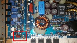
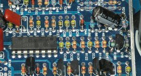
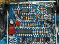
First, it looks like the cap is supposed to be connected to the screw hole, but it certainly looks like a hack.
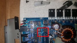
Second, U11 has a component soldered to pin 3. It looks like a decent solder job, but is still non-standard.
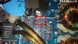
Third, R186 looks like it was floating around the amp. This is the only spot I could find that looks like a resistor was there, but is not now. The resistor I found floating around looks like a 240 ohm resistor, but I cannot confirm where it came from. Can someone confirm R186 is a 240 ohm resistor?
I have not tested the amp farther as I wanted to get the obvious taken care of. Half of the output section is shorted, so I will pull the outputs before I try to power it up.
http://www.diyaudio.com/forums/car-audio/277365-sundown-saz-1500d-help-identifying-zener-diodes.html
http://www.diyaudio.com/forums/car-audio/294369-class-missing.html
First, it looks like the cap is supposed to be connected to the screw hole, but it certainly looks like a hack.
Second, U11 has a component soldered to pin 3. It looks like a decent solder job, but is still non-standard.
Third, R186 looks like it was floating around the amp. This is the only spot I could find that looks like a resistor was there, but is not now. The resistor I found floating around looks like a 240 ohm resistor, but I cannot confirm where it came from. Can someone confirm R186 is a 240 ohm resistor?
I have not tested the amp farther as I wanted to get the obvious taken care of. Half of the output section is shorted, so I will pull the outputs before I try to power it up.
Attachments
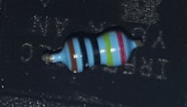
Thanks Perry. Interesting that the resistor I found floating around is not that one. Also, it looks like I have R186 and R187 missing from my amp. R187 looks like nothing was ever there. Which way do you read those resistors? They look symmetrical in their color banding, and it makes a big difference in the value depending which way you read it!
") I'll get the right resistors in there, pull the outputs, then see where the amp stands.
I'll get the right resistors in there, pull the outputs, then see where the amp stands.So one side of outputs were all shorted. I pulled them out of the board, but the question is can the amp be powered up with half of the outputs removed? I'm guessing not as it would control either the positive or negative half of the signal. I could pull the rectifiers to remove the high voltage, but will this still power up the rest of the output section to even see if I have any other issues there? The drivers seemed to bug OK (KTA1715/KTC2814 pair) with a multimeter.
When you say drive a strong 100Hz signal, do you mean just into the regular RCA input? I did that with a 3V peak to peak 100hz signal with the gain knob on the amp turned all the way up and I do not see anything that looks like a drive signal on the output transistors. The +15 and -15V regulators are working fine. Protect light is not on. On the driver board, these are the voltages I see. Pin 1 is considered the farthest left as you are facing the board. Ground reference is chassis ground. I do still need to install the 2 missing resistors, but they have not arrived yet.
Driver Card:
Pin 1: 0V
Pin 2: 7.8V
Pin 3: 0.4V
Pin 4: -2.8V
Pin 5: -2.8V
Pin 6: -2.8V
Pin 7: 9.36V
(gap)
Pin 8: My 100Hz test tone. It varies with gain/signal level. Clips at +/- 3.75V
Pin 9: 0V
Pin 10: 14.7V
Pin 11: 0V
Pin 12: -14.5V
Pin 13: 400mV
Driver Card:
Pin 1: 0V
Pin 2: 7.8V
Pin 3: 0.4V
Pin 4: -2.8V
Pin 5: -2.8V
Pin 6: -2.8V
Pin 7: 9.36V
(gap)
Pin 8: My 100Hz test tone. It varies with gain/signal level. Clips at +/- 3.75V
Pin 9: 0V
Pin 10: 14.7V
Pin 11: 0V
Pin 12: -14.5V
Pin 13: 400mV
Did you bridge IC! pins 1 and 2?
Yes I did. I actually bridged it at a capacitor and resistor right below IC1 because it was easier to get to, but I followed the traces up to pins 1 and 2 of IC1 (5532 opamp I believe). I also used a multimeter to verify the short on pins 1 and 2 of IC1.
Do you have the test signal present at pins 1/2 of IC1?
If I have pins 1 and 2 jumpered, I do not see my test signal. Resistance to ground is 14k (just checking for a short). If I remove the jumper, I get -13V on Pin 1 with no signal applied. With signal applied I get a +13V to -13V square wave at the signal generator frequency. Pin 2 looks like 0V when no signal is applied. When signal is applied it is a +600mV to - 600mV "square" wave at my signal generator frequency, but the signal looks like it has some good high frequency content riding on top of it making it look pretty bad.
IC1 does get warm (~65C) when jumpered and ~60C when not jumpered.
There is a comparator underneath IC1 (IC2) that was also getting semi-warm. I checked the output on pin 12 and that looked good, but I can't get to the other output. When I checked TR1 and TR2 (looks to be the drive transistors), they both diode checked OK. The NPN (TR1 MPSA42) had 15V on the collector, and both the base and emitter had 0 to 10V square waves. The PNP (TR2 MPSA92) had a 0 to 3.5V square wave on all pins. I'm not sure what to make of that. Not sure if that points me still to the comparator (IC2) or the PNP (TR2). TR2 does not bug as a short, so I'm not sure what else would cause it to look bad besides IC2.
Thoughts?
I don't think IC1 should be heating like that, jumped or not. It could be defective.
If pin 1 (the output) in the non-shorted case shows a strong, clean rail to rail signal, wouldn't that indicate it is working properly enough to at least get a signal out? Or is a square wave not what it is supposed to be putting out? I couldn't trace everything due to space, but I think IC1 feeds into IC2. One side of the driver transistors look OK, but one does not. Wouldn't both sides be bad if IC1 was bad?
Bringing this thread back. I also found a resistor R204 that looks like it was there at one point but is not anymore. Can you send me another picture with that value? It is just off the screen up and right of the picture you sent earlier. It is right by the LM293N comparator.
Also wondering if you had any insight into the previous post. I will get some parts on order, but I'd rather only replace the parts necessary on that driver board as it can be a little bit of a pain to get to some of the chips.
Also wondering if you had any insight into the previous post. I will get some parts on order, but I'd rather only replace the parts necessary on that driver board as it can be a little bit of a pain to get to some of the chips.
See attached.
Thanks. I'll get the known resistors on order along with the JRC5532 and JRC319 IC's. I'll go about replacing just the JRC5532 first and see if that makes a clean drive signal at that point.
NJM is the likely prefix. JRC is the manufacturer.
Yep, found that. the NJM5532 were readily available, the NJM319's were not. I ordered a LM319 as a substitute if necessary and I'll make it fit if I have to go that route. When the parts come in, I'll report back.
So I got the parts in, but I still have issues. I replaced the NJM5532, the NJM319, MPSA42, MPSA92, and IR2113S on the driver board. The NJM319 was replaced by a LM319, the MPSA42 by a KSP42, the MPSA92 by a KSP92, and the IR2113S by an IRS2113S. I could not find the exact originals so I went with things that I thought were appropriate replacements. Tell me if you don't think that is the case. I did not replace the MC14070B. Everything else on the driver is passive and those parts all looked good.
I also reinstalled all of the other parts (rectifiers and the new 4 output FET's). When I power it up, it does not go into protect, but there is a slight squeal coming from the board. I have it current protected and this was with no speaker load, so I felt comfortable with this configuration.
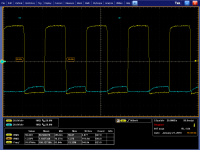
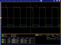
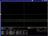
On the top half of the output FET's, the gates looked normal. The new replaced bottom half still looks bad. Channel 1 is top, Channel 2 is the bottom
I looked at the bases of the driver BJT's and they look similar. The bases are tied together between the PNP and NPN's it seems.
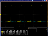
I started going back up the line to the IRS2113S then to figure out where my problem might lie. I checked the HIN and LIN pins of the IRS2113S and they look OK to me.
When I look at the HO and LO pins, I see the problem coming back. I assume the IRS2113S is OK as I just replaced it. I bugged the drivers with a multimeter previously and they seemed OK. They bug similar to the "good" top side. They are the only components I can think of that are still in line that are not new.
The original drivers are an NPN KTC2814 and PNP KTA1715. I could not find these as an exact replacement so I didn't order them initially. Would the KSC2690A be an appropriate NPN replacement and the KSA1220A be an appropriate PNP replacement?
Are there any other things I should be trying to look at?
I also reinstalled all of the other parts (rectifiers and the new 4 output FET's). When I power it up, it does not go into protect, but there is a slight squeal coming from the board. I have it current protected and this was with no speaker load, so I felt comfortable with this configuration.
On the top half of the output FET's, the gates looked normal. The new replaced bottom half still looks bad. Channel 1 is top, Channel 2 is the bottom
An externally hosted image should be here but it was not working when we last tested it.
I looked at the bases of the driver BJT's and they look similar. The bases are tied together between the PNP and NPN's it seems.
An externally hosted image should be here but it was not working when we last tested it.
I started going back up the line to the IRS2113S then to figure out where my problem might lie. I checked the HIN and LIN pins of the IRS2113S and they look OK to me.
An externally hosted image should be here but it was not working when we last tested it.
When I look at the HO and LO pins, I see the problem coming back. I assume the IRS2113S is OK as I just replaced it. I bugged the drivers with a multimeter previously and they seemed OK. They bug similar to the "good" top side. They are the only components I can think of that are still in line that are not new.
An externally hosted image should be here but it was not working when we last tested it.
The original drivers are an NPN KTC2814 and PNP KTA1715. I could not find these as an exact replacement so I didn't order them initially. Would the KSC2690A be an appropriate NPN replacement and the KSA1220A be an appropriate PNP replacement?
Are there any other things I should be trying to look at?
Attachments
- Status
- This old topic is closed. If you want to reopen this topic, contact a moderator using the "Report Post" button.
- Home
- General Interest
- Car Audio
- SAZ-1500D V2 Repair Questions