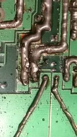
I have found the problem. When I added the extra solder to increase the current carrying capability I swallowed up the resistor end pin. It's in the center of the image. Looks rather a mess.
I will have to purchase a new resistor and go again.
Transformer of course, not sure why I'm calling it an inductor.
Thanks again. Will try again in a few days.
I will have to purchase a new resistor and go again.
Transformer of course, not sure why I'm calling it an inductor.
Thanks again. Will try again in a few days.
Attachments
Hi Perry. I take your point about testing it, but I wanted it fully repaired before that.
I have fully replaced all known parts. All power supply transisters are 3205, and all output fets are IRF540N
My power supply is a battery charger set at 6v, giving 8.8v. It's the best I've got other than a car battery.
I have a red light on.
I have a mid pitched buzzing, from the transformer. A bit too loud for my liking but the board is not in it's case. Sounds more like fat frying.
I have 19 volts on the common cathode diode relative to battery earth and -14 on the common anode
I have all four power supply fets slowly warming up, in about 60s they are hot to touch.
The two on the left get hotter than the two on the right.
All output transisters are cold.
A good start. Concerned about the voltage not being even. I did buy two new rectifying diodes.
Please can you tell what I should do next?
The charger likely has an unfiltered output and will cause noise problems.
In testing, you want to limit the current initially. This can be done with a large resistor, a headlamp (H6054, both filaments in parallel) or by using a fuse (10-25 amp, depending on the amplifier). You also need to clamp all components down to prevent them from overheating and failing.
The shield ground under the RCA jacks is also likely to break on these amps.
Ah, ok, that makes sense. I used it because it's got a ammeter display so could watch the amp starting up. I did use a lightbulb as you suggest in your guide.
The RCA is good on this amp.
I've bolted down the transistors, still concerned about that imbalance in the power supply. All four transistors were from the same batch.
The RCA is good on this amp.
I've bolted down the transistors, still concerned about that imbalance in the power supply. All four transistors were from the same batch.
If you have a scope, compare the drive signals on the gate legs of all of the power supply FETs.
I don't have a scope Perry.
In the 6v setting it makes 9v, in the 12v setting it makes 20v.
At 20v the FET heating is more pronounced but nothing scary. I'm just concerned that two of the FET's are running hotter than the others and there is that slight imbalance in the voltages. I will look to understand the circuit more completely and see if any of the replaced components have sister components that may be slightly damaged.
I think I will try it off a car battery next to remove any chances that the 1970's battery charger is causing problems. This will probably be in a few days as I have to take a trip.
Many thanks for your help so far.
I was concerned about the drive circuit but if all FETs have the same exact voltage, it 'may' be OK. You need to look into getting a scope. You'll likely buy from ebay. Email me the auction numbers and your budget when you decide to buy.
babin_perry@yahoo.com
Install a single 15 amp fuse and have all components tight to the sink before connecting it to the battery.
babin_perry@yahoo.com
Install a single 15 amp fuse and have all components tight to the sink before connecting it to the battery.
Hi Perry, cannot afford to buy a scope at the moment, even a laptop scope for £50 pounds sadly.
I have tried the amp and it didn't go well. One channel fried a mosfet, but did work for a time. Fan kicked in and the protection kicked in too.
The other channel heated up all it's output resistors very quickly and did not do any amplification.
I have considerably different resistances when I measure the across the two speaker terminals for each channel.
I think it's out of my hands until I have the funds for proper test equipment.
Many thanks for all your help. I look forward to phase two once I am back in work.
Regards, Jonathan
- Status
- This old topic is closed. If you want to reopen this topic, contact a moderator using the "Report Post" button.
- Home
- General Interest
- Car Audio
- MTX Thunder 2300 board photographs needed