Unit does not power up or give a light,totally lifeless.Both 3525s were faulty due to the reference (pin 16) sitting at 1-2 vdc and running abnormally warm with correct b+ and ground,measured at ic pins.Even lifted pin 16,no change.
Q66,68 mosfets (2n7000) were shorted amongst 2 pins out of circuit.
Q69 also shorted
Seems q63 dictates voltage for pin 13 of 3525.Those were replaced as well(both q63's) although tested fine.
Amp did power up a couple times after above stated faulty parts were changed and seemed okay as far as regulated voltages,power supply gate drive etc.
The 4-5 attempt to restart it,it failed to start.Drawing practically zero current with remote connected.Have not located another faulty part as of yet.
Seems the problem lies with lack of voltage to pin 13 of 3525.Getting a little stuck on tracing the circuit from q63.
3525 voltages
1.2.5v
2.100mv
3.0
4.300mv
5.2v
6.3.6v
7.2v
8.4.8v
9.100mv
10.0
11.0
12.0
13.100mv
14.0
15.13.5v
16.5.1v
While the amp fails to start,scoping the 3525shows no problems.Both are running ~ 30khz and have 5.1v at pin 16
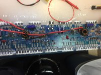
Attachments
Something is keeping the pnp transistor (one with its collector tied to pin 13) base terminal high,keeping it from conducting.Atleast that's what I'm getting out of it.
I'm thinking a form of protection is controlling voltage at pin 13?
Although no indication of protection is given.The single led it has only illuminates when it's running normally it seems.
Oddly this thing did work for a couple moments after the parts listed were changed.But none of those same parts are bad again.
This board is basically two amps on the same board.Know if it's possible to power half of it?
Hasn't worked this far just trying to power half.Although the B+ might be tied amongst the two.Not sure if that will help much anyways.
I might have to draw the circuit out to grasp the pin 13 dilemma pending any other ideas.
On some of the amps, you can power only 1 red wire.
Are any of the thermistors shorted?
You may be able to pull the transistor that's pulling 13 down. At 12v in, it may produce excessive rail voltage so be careful if you try it. Reducing thee 12v supply voltage may help limit the rail voltage.
Are any of the thermistors shorted?
You may be able to pull the transistor that's pulling 13 down. At 12v in, it may produce excessive rail voltage so be careful if you try it. Reducing thee 12v supply voltage may help limit the rail voltage.
Removed transistor that controls pin 13 and jumped b+.It appears to be operating okay.
Still need to find out why it won't power up with the transistors installed.
Do yo know what the purpose of the little chokes by the 3525's is?It appears the drive signals go through the chokes marked FC from the 3525 directly to the gate resistors of the power supply fets.
Seems like a fairly large drive load without drivers but apparently it has worked.
Also there are test points on the board.Tdr1/2,oc etc Know what the abbreviations mean and what voltage is expected at the various points?
- Status
- This old topic is closed. If you want to reopen this topic, contact a moderator using the "Report Post" button.
- Home
- General Interest
- Car Audio
- Ppi mos-450