Xenon 11.5k amplifier output driver card poosible fault, or error in test procedure
Hi just found this thread here.
http://www.diyaudio.com/forums/car-audio/265645-output-driver-card.html#post5143770

What is the pwm frequency supposed to be?
I have 2kHz pwm with 0us dead time. Everything appears OK but it blows output devices. Totem poles all OK as far as I can tell.
It is the same board as rrae's picture, included above.
Thanks
Simon
Hi just found this thread here.
http://www.diyaudio.com/forums/car-audio/265645-output-driver-card.html#post5143770
What is the pwm frequency supposed to be?
I have 2kHz pwm with 0us dead time. Everything appears OK but it blows output devices. Totem poles all OK as far as I can tell.
It is the same board as rrae's picture, included above.
Thanks
Simon
Last edited:
Further to this,
The output only pops when both halves of the output are installed - i.e. each side of the amplifier is driven from one IRS21844 and 1 set of 16 totem poles.
I have used my bench supply to power up the output stage only, with +/- 39V rails and -ve Rail+12 and +/- 15V for the preamp/driver stage.
Also I put isolated 12V supply in each side for the high side driving of the IRS21844.
The totem poles have a healthy 12v (low side referenced to rail, high side referenced to output terminal).
Do I need to also connect the output to a load in the absence of the FETs?
Thanks
The 2k isn't the carrier frequency. Some amps will produce it and some will not, when the circuit isn't complete.
Drive a 50-100Hz signal into the amp and follow the signal to the output gate pads. I don't know this particular amp but in most amps that use similar circuits can be better tested for drive signals when the rectifiers are removed because you can have the output FETs in the circuit to load the drive circuit.
Drive a 50-100Hz signal into the amp and follow the signal to the output gate pads. I don't know this particular amp but in most amps that use similar circuits can be better tested for drive signals when the rectifiers are removed because you can have the output FETs in the circuit to load the drive circuit.
Thanks guys, will do further testing later in the week.
Is there an easy way to trick the circuit to oscillating correctly?
I have put a 1nf capacitor between gate and source on a few of the pads to load the totem poles, and they still drive ok to that load.
As mentioned, it seems to work when one "pair" of fets or the other is installed, but pops when both "sides" are installed - even only one FET per totem pole set.
IT won't oscillate at the normal high frequency unless the circuit is complete.
Connect a 10k resistor between pins 1 and 2 of the TL072 (wherever you can easily solder it into the circuit). Remove the rail supply and that will allow you to directly connect the scope to the output FETs with no risk to the FETs. You should see a square wave of whatever is driven to the amp at all output FETs.Having the 10k resistor will allow you to see a square wave all of the way through the circuit.
Connect a 10k resistor between pins 1 and 2 of the TL072 (wherever you can easily solder it into the circuit). Remove the rail supply and that will allow you to directly connect the scope to the output FETs with no risk to the FETs. You should see a square wave of whatever is driven to the amp at all output FETs.Having the 10k resistor will allow you to see a square wave all of the way through the circuit.
Thanks Perry,
How can I check the Dead Time with this test setup, as I think that may be the problem?
Is it as simple as ramping up the input to the TL072 to 90kHz?
The 10k resistor will be bypassing C6 feedback capactor.
(it's pin 6 + 7 on these amps, as it uses the 2nd op-amp in the package.
Thanks for your help.
Last edited:
Unless you inject signal at the driver board, you can only use lower frequencies for testing. Low frequency testing (50-100Hz) is generally good enough to determine if all components are working as they should be.
The deadtime is determined by the 21844. If you check it, it will have to be after the 21844. I've never had the deadtime be a problem on an amp using a 21844.
OK on the 'pins 6 and 7'. I'm going by similar amps. I've never had to repair one with this driver board.
The deadtime is determined by the 21844. If you check it, it will have to be after the 21844. I've never had the deadtime be a problem on an amp using a 21844.
OK on the 'pins 6 and 7'. I'm going by similar amps. I've never had to repair one with this driver board.
Make sure the resistors near the driver card are all in spec. There are some 1ohm or 4.7ohm resistors that sometimes open with no visible damage. With one defective the outputs will continue to fail when powered up until replaced. Are you using a new driver card, or have you replaced the 21844's on that one?
Actually, the amp works. The owner was using it, but one side of the amp gets hot very quickly. With no speaker connected.
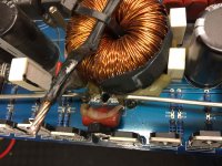
I just found one the 2 inductors, had one connection totally burned off the PCB, no electrical connection at all.
This is the side that was overheating, but I am pretty convinced the Mosfets (24N50) , were overheating.
Do you think the Mosfets would overheat if no connection to the inductor?
I just found one the 2 inductors, had one connection totally burned off the PCB, no electrical connection at all.
This is the side that was overheating, but I am pretty convinced the Mosfets (24N50) , were overheating.
Do you think the Mosfets would overheat if no connection to the inductor?
Attachments
Perry,
I didn't see evidence of that, I wish I would have thought to take a picture of the condition before I pulled the wire off the PCB.
I did ohm the coil to the PCB, totally open, and the coil read 80uh. I would not have expected that disconnection of the circuit, would have caused the overheating condition either.
Let me tell ya, an amp drawing 102 amps while troubleshooting isn't exactly in my comfort zone.
- Status
- This old topic is closed. If you want to reopen this topic, contact a moderator using the "Report Post" button.
- Home
- General Interest
- Car Audio
- Xenon 11.5k amplifier output card driver