When I got this amp R1029 was burned open which is between the negative regulator and the TL072 op amps. I found U7 a DG201BDY on the EQ card was the problem and replaced it and the burned resistor. I have good voltages on all the regulators now and the amp produces audio however not clean, the amp is still not right.
With gain all the way down, input signal, and no load it draws ~2.5A at idle with about .090VDC offset at the speaker terminals. The outputs get warm after several minutes of idling. As I turn the gain up, the current draw reduces and the DC offset climbs. At max gain, the current draw is ~1.6A and the DC offset is about -5.8VDC while the ACV is above 60VAC at the speaker terminal.
The bass boost control does make the current draw lower as it is increased. The crossover does make the current draw higher IF I attenuate the input signal. The input frequency also seems to make a difference, higher is better, to a point. The subsonic switch does not seem to matter, on or off.
Any suggestions for what I am missing?
Attachments
![IMG_2134[250].jpg](/community/data/attachments/585/585327-9333f44aad92ba113c9a55ced69bc140.jpg)
I ended up changing out U3 right behind the RCA jacks because the signal didn't look very good there. The DC offset swing with the gain control position seems to be resolved. The audio signal on the output terminal looks much cleaner.
It still draws ~2.5A at idle, no signal, no load and maintains its ~.090VDC offset throughout the gain control range. Is that normal for this amp? Both seem a tad higher than I would expect.
It still draws ~2.5A at idle, no signal, no load and maintains its ~.090VDC offset throughout the gain control range. Is that normal for this amp? Both seem a tad higher than I would expect.
Still looking at this amp.
I wired up a subwoofer to test and it sounds fuzzy, slightly distorted.
With scope ground on the negative speaker terminal, I have clean signal at pin 3 of U3. At pin 1, it is not as clean. Signal at the output terminal is similar to that at Pin 1.
I changed the TL072 again at U3 but that made no difference.
I have attached pictures to help show what I am seeing, but they may not be high enough of quality. First pic shows Pin 3, second pic shows Pin 1, and the last pic shows the output terminal. Only change to scope was the V/div on the output terminal. A 4 ohm dummy load was connected to the output terminal for all pictures.
I think that getting this signal cleaned up would probably help reduce the idle current draw some. What should I be looking for?
Attachments
Last edited:
When looking at signals, you generally want as much resolution as possible. Set the scope so that the waveform extends at least 3 major divisions vertically. 3-4 cycles (as you have it) is a good start for the timebase setting.
Sometimes you can see distortion if you set the timebase so that there are so many cycles displayed that you cannot see the individual cycles. For a sub amp, this may require setting the crossover to the highest point and driving a higher frequency signal into the amp (near the highest crossover setting).
Sometimes you can see distortion if you set the timebase so that there are so many cycles displayed that you cannot see the individual cycles. For a sub amp, this may require setting the crossover to the highest point and driving a higher frequency signal into the amp (near the highest crossover setting).
Last edited:
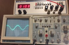
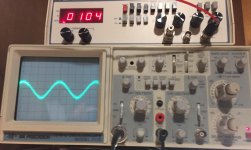
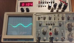
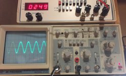
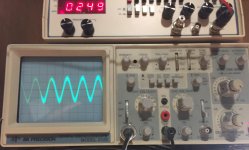
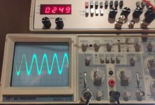
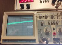
Here are some new pictures. The setup is with low pass crossover set as high as it will go at 250Hz. Gain down all the way, subsonic off, bass boost at minimum, 4 Ohm dummy load connected.
First picture is of the clean signal on pin 3 of U3.
Second picture is of pin 1 of U3.
Third is of the output terminal, again only setting change was Volts/Div.
Fourth with Time/ Div set to show the high frequency riding on the audio. Sorry, I forgot to note the Time/Div it was set at and I have since moved it.
I tried setting the Time/Div slow and adjusted the input frequency as high as 1200Hz to get the "band" across the scope but I didn't see the distortion like I have on a/b amps. I couldn't get a good picture of that scope setting.
Attachments
- Status
- This old topic is closed. If you want to reopen this topic, contact a moderator using the "Report Post" button.
- Home
- General Interest
- Car Audio
- Rockford Fosgate P1000-1bd