I don't have your answer, but I do have some advice.
When you find the right parts to replace the dead ones with, you really ought to have a think about what caused them to fail in the first place.
Diodes and resistors do not (generally) spontaneously combust - I am not being cheeky here...
Diodes and resistors are really very reliable parts. Resistors almost always fail open circuit (and not catch on fire). Diodes are just super reliable except where abused.
Both diodes and resistors generally fail when something else has failed and is drawing too much current. Capacitors and big semi's being common culprits. Before you swap these out, it would be instructive to get a hold of the schematic, which by the way will answer your initial question, and look around for what else might be at fault in there.
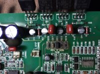
The resistors are 6.8k. The diode is a 12v Zener (PTZ12B - check dimensions).
http://www.mouser.com/ds/2/348/ptz12b-220154.pdf
http://www.mouser.com/ds/2/348/ptz12b-220154.pdf
Ive replaced the parts that was missing, i didnt replaced the zener diode as it checked off good, the amp is playing but only with minimal gain, when i adjust the gain control knob it cuts off to protection and wont resume until i minimise the gain knob fully. There is nothing been overheated and no DC volts on the output. i even bypass the audio input opamp board and put audio to the input pin on the main amp board and still chips to protection only plays with limited or low attenuation. is there any possibly suspects or pin test that can used to temporary disable the protection circuit?
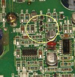
It plays as expected when removed the Q04, Played it for minutes even without the heat sink at 50% gain adj and it seems efficient and stable.
However, what could be causing it to protect with such minute sensitivity? The collector of Q04 goes thru R09 (4.7ohms) to the DTC pin on the 494chip, if increasing the value of the resistor will that decrease the sensitivity?
However, what could be causing it to protect with such minute sensitivity? The collector of Q04 goes thru R09 (4.7ohms) to the DTC pin on the 494chip, if increasing the value of the resistor will that decrease the sensitivity?
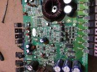
What section of the amp I find D15 and D16? The closest I’ve seen is D13 and D14 which I think is the two coupling diodes on the gate drive circuit for the power supply mosfets. I don’t know if those that you ask is under the silicone glue which is holding the toroidal PS transformer.
Attachments
- Status
- This old topic is closed. If you want to reopen this topic, contact a moderator using the "Report Post" button.
- Home
- General Interest
- Car Audio
- Kicker KX600.1 burnt parts