i was thinking about that too perry, ill just hold on to them. Yeah i ordered extra on everthing, smd's more than enough (for later). and that is ithe difference in the amps, the professional version 24db slope..... vrs the 12db. Im keeping this amp for myself. i got 2 5oz tubes of 340 for 32.00 also coming, do you like the thermal tape, i see it alot anymore on amps or is the greese still more effective, or both>
If there are hard insulators, you have to use the heatsink compound. It's not necessary on new silicone tape but I use compound when re-using the silicone tape.
When you apply the compound in your amp, apply it to both the MEHSA insulator and the heatsink. A thin layer on both surfaces is better than a single thick layer because the insulators will flex and won't disperse the compound evenly.
When you apply the compound in your amp, apply it to both the MEHSA insulator and the heatsink. A thin layer on both surfaces is better than a single thick layer because the insulators will flex and won't disperse the compound evenly.
Those will work but you don't need such expensive resistors. Something like the 311-20ARCT-ND would be fine. The expensive ones are OK when you order just a few but if you do repairs and have to order many hundreds of resistors for stock, the more expensive ones are difficult to justify the cost.
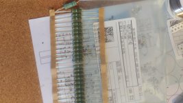
The size/power rating is partly dependent on the material they're made from. Larger resistors will run cooler but sometimes a smaller resistor is needed for the allotted space so higher temperature withstanding materials are used. The ones you have should be OK. In the future, match the size if you want them to look the same.
You don't need to order these. They are what I use but are expensive (especially when you need so many). LVR03R1000FB12 (mouser).
You don't need to order these. They are what I use but are expensive (especially when you need so many). LVR03R1000FB12 (mouser).
So i have most of the smd resistors tested and swapped, i am waiting on the 20 Ohm to finish, the transistors are all on the rail and sodered, Source resistors back on the board (They came out nice). the drivers are removed. So much better to remove the rail and use a flat skillet in the rail to preheat, it not the prettiest job but there are solid. heat gun and my iron to set them. Just waiting on the resistors they should be here tommorow. All in all not the best looking sodering job on the transistors. Once the resistors come ill replace everyone recommended on the scheme you sent me. Should i go ahead and replace those 8 ps transistors? And what i should i do first after perry, Resisted B+, Or some other test?
Leave the power supply alone if it's undamaged.
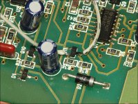
Jump the transistor Q11 as shown in the attached image.
Use the resistor in the B+ line.
Set both bias pots fully counter-clockwise before applying power.
I meant to tell you to do one channel at a time. I forgot to do that in a previous post. Start with the 200 series channel. To disable the 300 series channel, lift Q301.
Attachments
You can't connect a load or speaker until you're sure that the channel appears to be working correctly (check for DC with a meter or look at the output with a scope). If it was a small speaker, you should have had a capacitor inline.
Jumping Q11 allows you to use a current limiter and that should allow you to see if it's drawing excessive current before any outputs fail.
Jumping Q11 allows you to use a current limiter and that should allow you to see if it's drawing excessive current before any outputs fail.
Test for DC across the two speaker terminals for the channel.
I'd recommend a 2 ohm, cylindrical wirewound resistor rated for 100w.
http://www.mouser.com/ProductDetail/Ohmite/L100J2R0E/?qs=06/EEXcdZWQyq%2bVjS1rN4g==
I'd recommend a 2 ohm, cylindrical wirewound resistor rated for 100w.
http://www.mouser.com/ProductDetail/Ohmite/L100J2R0E/?qs=06/EEXcdZWQyq%2bVjS1rN4g==
ok perry i ordered some 51 ohm 0805's (i didnt have any) and the resistor $$, Im sure ill get alot of use out of it. how many of the outputs should i replace, being the one is shorted, the others seem ok? Or should i just replace them all and all the drivers? Or just replace the shorted one and the driver set for them, and test each channel?
- Status
- This old topic is closed. If you want to reopen this topic, contact a moderator using the "Report Post" button.
- Home
- General Interest
- Car Audio
- Rockford Fosgate 800a2 Repair Help