I forgot to answer your earlier question Perry. Yes, I'm fairly sure the big bang has to-220 drivers on the pwm card. I think it also runs irf064 outputs as well. I was only mentioning it to point out that I have a relatively small sample set for testing. Ik the cards with to-220s are worse for some reason. I'll definitely use that amp for a sizeable portion of the testing.
I'm pretty sure that particular amp is not deep enough for my new card though. I've found that in several amps there is room to run the card lying flat (instead of 90° header) as long as you are also willing to socket it. I'm somewhat surprised that the factory didn't ever attempt this layout. You get worlds better air circulation across the card in that position. I can submit pictures tomorrow if my description is unclear.
Thanks!
Jason
I wanted to know if the ksa1220 type transistors ran cooler than the TO-220.
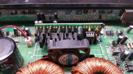
With the card as shown, it will cool better. The fgan draws from a very shallow depth on the intake side. The components have to be very close to be cooled by the fan. In amps where the inductors use better cores and the inductors run cooler, you can turn the fan around to blow on the driver board but those are rare.
One thing you could do if you lay the board down is to install a fan on the bottom cover. There doesn't need to be any intake hole. Stand the fan off of the bottom cover either with short standoffs or a couple of nuts on each corner. It will blow plenty of air and will be using internal air but having the moving air will make a huge difference in temperature.
The Sunon ME40101VX-000U-A99 is a little noisy but moves a huge amount of air for a 40mm fan.
Understood. My intention is to do some strictly controlled testing with the three factory versions VS my card. Its going to take me a few days to get things set up, but I plan to run each amp into a resistive load for xx hours and then take thermal images of the cards and possibly thermocouple data for the problem transistors of the thermal images are not conclusive. I just need a bit of time to get things all set up and going.
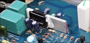
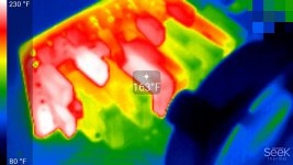
Well, I have had some time to do some testing. These photos are in a planet audio big bang 2400.1. All testing has been done with the amp inverted and the bottom off. The big bang is not deep enough to take my upgraded card in a socket.
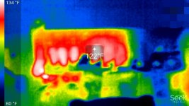
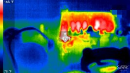
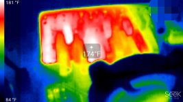
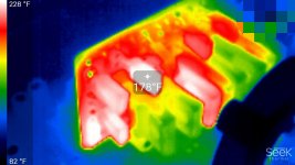
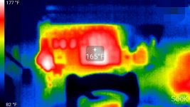
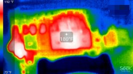
To start with, I adjusted my cards current source until the amp was drawing about 3a at idle. That is right in the ball park of what the stock card was doing. After about 10 minutes of music into a 2R load, the driver transistors in the problematic locations were thinking about 165°F. After a half hour they were pushing 180°F and leveled off on that range even after more than an hour.
I powered down and replaced it with the stock card. The stock card sat much closer to the fan due to the angle that the right angle pin header was soldered at, but temperatures at similar time points and otherwise identical conditions showed Temps about 10° lower than my card. I think this is due to it being close to the fan and the fact that I could only measure the edge of the transitor package due to the transistor orientation. On my card I'm able to shoot the back of the package basically right on top of the die.
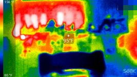
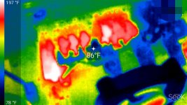
The next test surprised me. I used a very small scrap piece of 16g aluminum and I bolted it to my driver transistors. I used some snips and cut and bent some alternating fins to get a bit more surface area. I painted the fins black because bare aluminum does not photograph well in ir. At ten minutes that row if transistors was at 86°F. At the one hour mark it was only up to 96°F. I thought maybe I still didn't have a good ir radiating surface and was getting misleading results, but the makeshift heat sink was cool to the touch.
I'm more than happy with these results. I'm going to see if I can find a commercial heat sink solution, but if not I'll take the time to make something nice in the machine shop.
To start with, I adjusted my cards current source until the amp was drawing about 3a at idle. That is right in the ball park of what the stock card was doing. After about 10 minutes of music into a 2R load, the driver transistors in the problematic locations were thinking about 165°F. After a half hour they were pushing 180°F and leveled off on that range even after more than an hour.
I powered down and replaced it with the stock card. The stock card sat much closer to the fan due to the angle that the right angle pin header was soldered at, but temperatures at similar time points and otherwise identical conditions showed Temps about 10° lower than my card. I think this is due to it being close to the fan and the fact that I could only measure the edge of the transitor package due to the transistor orientation. On my card I'm able to shoot the back of the package basically right on top of the die.
The next test surprised me. I used a very small scrap piece of 16g aluminum and I bolted it to my driver transistors. I used some snips and cut and bent some alternating fins to get a bit more surface area. I painted the fins black because bare aluminum does not photograph well in ir. At ten minutes that row if transistors was at 86°F. At the one hour mark it was only up to 96°F. I thought maybe I still didn't have a good ir radiating surface and was getting misleading results, but the makeshift heat sink was cool to the touch.
I'm more than happy with these results. I'm going to see if I can find a commercial heat sink solution, but if not I'll take the time to make something nice in the machine shop.
Attachments
-
 UAC_top_row.jpg83.7 KB · Views: 54
 -
 UAC_Q112.jpg79.2 KB · Views: 39
 -
 1hr_UAC_HS.jpg93.7 KB · Views: 44
 -
 10m_UAC_HS.jpg90 KB · Views: 41
 -
 stock_card_1hr.jpg74 KB · Views: 41
 -
 stock_1hr_2.jpg73.2 KB · Views: 43
 -
 stock_10m.jpg75.7 KB · Views: 128
 -
 10m_UAC.jpg77.4 KB · Views: 128
 -
 1hr_UAC.jpg84 KB · Views: 142
 -
 IMG_20180703_142316433_HDR-2.jpg141.7 KB · Views: 92
- Status
- This old topic is closed. If you want to reopen this topic, contact a moderator using the "Report Post" button.
- Home
- General Interest
- Car Audio
- Generic Asian Clone driver board RE and Clone