Thank you Perry. When you said across the rail Caps, where exactly should I put may red lead of the VOM? Also, only the heat sink is attached right? No other parts of the cover( end plates, top, bottom).
I already removed the 3jumpers, replace all 8 PS resistors and PS FET's. I am ready to test the voltage with the inline 15 amp fuse. Please reply.
Thank you Darrel
I already removed the 3jumpers, replace all 8 PS resistors and PS FET's. I am ready to test the voltage with the inline 15 amp fuse. Please reply.
Thank you Darrel
Thank you Perry. Put the Heat Sink in place, a 15A inline fuse, power up and unable to get to leg 2 of the output transistor, measured across the output caps under the pcb, and measured 90VDC. Soldered the replacement transistors and hopefully tonight will put everything back together and test for sound.
Any other test before assembling everything back? Please reply.
Thank you again.
Darrel
Any other test before assembling everything back? Please reply.
Thank you again.
Darrel
Ia assembled everything with fresh heat conducting medium. Connected it where it was previously and played music for about 2 hours with nice pounding bass. Left it on for about 2 more hours eithout music, and at that time, it blew the 50 amp fuse. Tried a 30 amp and it worked for several seconds, not an instant current blow. Took it out, to get it back to the bench for evaluation. Do you think the replacement output transistors are not compatible with the driving system?
Please reply.
Thank you, Darrel
Please reply.
Thank you, Darrel
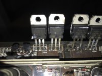
Thank you Perry. Sorry for the late answer but, today I was able to open the unit. The output transistors Q505 and Q506 look burned, see picture. This is limited to the legs. I wonder if I caused some kind of damage to the board, because some of the strands of the jumpers were still in the hole, so it was difficult for me to solder the new transistor.s I will take all 4 out and check if they are shorted. I will let you know. Darrel
I haven't had to replace any in that amp. The IRF3415 was reliable in a lot of 500s. I used the IRF3710Z in the 500s but the 90v rail in this amp is a bit too close to the max 100v of that transistor (I'd be concerned, even though the originals were 100v).
If anyone has a proven (not only 1 or 2 repairs) sub that works, they should post what they used.
If anyone has a proven (not only 1 or 2 repairs) sub that works, they should post what they used.
Thank you Perry. I will order 4 of both, and make sure the PCB is ok. The heat sink is so close to the soldered area that maybe they became grounded. Usually the reason for getting this transidtor shorted is either high voltage or high amps? Can you think of something else that is pushing these FET's to the limit? This power is driving 2 JL 10" subwoofer in parallel. They are both 4 ohms. It worked ok for 2 years +.
I'll order the parts and try again. Is there any way to buy the schematc of this unit or the 500/1 which is very similar?
Please reply, thank you. Darrel
I'll order the parts and try again. Is there any way to buy the schematc of this unit or the 500/1 which is very similar?
Please reply, thank you. Darrel
JL doesn't release schematic diagrams.
Transistors can be damaged by excessive voltage (unlikely in this situation) or overheating of the internal die. Overheating can be caused by poor mating to the heatsink, a poor quality drive signal or too much current passing through them. Before you power the amp up normally, go back and test as suggested earlier (remote on for a couple of seconds then test within 10 seconds). This will allow you to see the drive signal with the outputs loading the drive circuits but won't allow the rail supply to power up. Testing before the main supply powers up helps protect the outputs if there is a bad drive signal.
You may want to give another day or so to see if anyone has any other suggestions for substitute outputs.
How did that go I currently am attempting a repair on a 600/v3 and xd1000/1v2 was wondering if changing caps or any other upgrades can be done...and also having trouble finding the ntp6413ang mosfet ......but was curious to see if I could use "better" one throughout the board
- Status
- This old topic is closed. If you want to reopen this topic, contact a moderator using the "Report Post" button.
- Home
- General Interest
- Car Audio
- JL 600/1 v3 failure