Yes, That is what I did several times. I also attached the ground cable of the Oscilloscope to the negative of my 12v power supply. The first pad 504 was about 14v I believe, but the next was 0 and if I wait to the end it will jump momentarily to about 4v. The 3rd was like double the first, and the last one was 0 even at the end of the cycle. I will repeat the test tonight with more precise information.
I never used the alligator clip because I attached the cable to the ground of the Oscilloscope and to the neg of the power supply.
I've never seen a sinusoidal wave with this Oscilloscope. I think the defective part of the unit is the one behind the unit (means ME). I may not be using it correctly.
Thank you again, I hope the drivers and the Pulse width modulated are ok.
Darrel
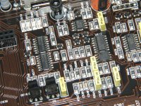
I don't know if your board will be the same as the one below. If it is, solder a bridge between the two pins in the orange circle and try looking for the signals again.
You MUST remove the jumper before powering the amp up with the outputs in the circuit.
You MUST remove the jumper before powering the amp up with the outputs in the circuit.
Attachments
Thanks Perry for your help. With the trace adjustment the tilted display is back to normal with the Hitachi. I couldn't get the square wave in any of the pads. After jumping the chip shown in the pervious photo, I got a square wave with 2.97 volts at Q504 and Q507. Q505 showed a distorted band in the display, which I was unable to adjust to get some kind of wave. Q506 showed a square wave with 4.95vdc.
Would you say that the PWM and driver transistors for the output are ok? Would I need to just change the output transistors as well as the power supply transistors? So far the circuit board had been the same as the JL500/1/
Thank you again.
Darrel
Would you say that the PWM and driver transistors for the output are ok? Would I need to just change the output transistors as well as the power supply transistors? So far the circuit board had been the same as the JL500/1/
Thank you again.
Darrel
Ok I will do that tonight. What would happen if I let the unit in the ON mode to see if I can adjust the Hitachi to get a wave form from Q505? I get about 10 secs. or less before the current stop. With the adjustment I used to see the wave of Q504 and 507, I get a thick band about 1 volt with different densities vertically. I will also measure the dcv at that pad, which I haven't done.
I notice I needed a lot of heat to remove the transistors. Those are soldered to huge bar of aluminum and copper on the board. Do you still use the WIS50 for that application?
Thank you Perry, will keep in touch.
Darrel
I notice I needed a lot of heat to remove the transistors. Those are soldered to huge bar of aluminum and copper on the board. Do you still use the WIS50 for that application?
Thank you Perry, will keep in touch.
Darrel
They come out easily with the WES51. If there are no burrs on the legs of the transistors, apply enough new solder and lay the iron across all 3 legs. When all are hot (solder molten), they will fall out or can be pulled out with very little force.
I generally do it as I suggested because it prevents the main supply from switching on. If there are no power supply FETs in the amp, I think it will work if you leave the remote attached.
Try adjusting the trigger level and trigger coupling.
I generally do it as I suggested because it prevents the main supply from switching on. If there are no power supply FETs in the amp, I think it will work if you leave the remote attached.
Try adjusting the trigger level and trigger coupling.
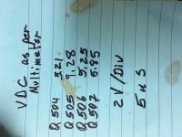
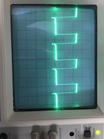
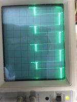
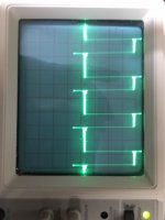
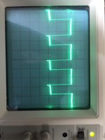
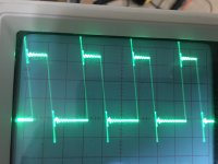
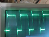
Got all square waves. Vdc varies though, when measured with a digital multimeter. Images for each gate leg attached from Q504 to Q507.
Tell me what you think, would you say the variation in voltage is an instrument problem?(square wave measured in dc) or is there something wrong with the transistor drivers?
Please reply, and thank you for your help.
Darrel
Tell me what you think, would you say the variation in voltage is an instrument problem?(square wave measured in dc) or is there something wrong with the transistor drivers?
Please reply, and thank you for your help.
Darrel
Attachments
Earlier, you stated that there were discolored resistors. Were they within tolerance?
Do the waveforms on pins 5 and 7 of U500 look the same? To prevent shorting pins together, it may be easier to touch the probe to R514 and R515 (the ends directly connected to pins 5 and 7 -- confirm connection with ohm meter with no power applied)
Do the waveforms on pins 5 and 7 of U500 look the same? To prevent shorting pins together, it may be easier to touch the probe to R514 and R515 (the ends directly connected to pins 5 and 7 -- confirm connection with ohm meter with no power applied)
Would you say that replacing the Power FET's and the Output FET's along with the Power FET's resistors will fix the unit?
The resistor of the power FET's are all open. As per color those are 10 ohm with 5% tolerance. Is that the same as the JL500/1? I think I read about a higher resistance on those.
Thank you very much.
Darrel
The resistor of the power FET's are all open. As per color those are 10 ohm with 5% tolerance. Is that the same as the JL500/1? I think I read about a higher resistance on those.
Thank you very much.
Darrel
You use the test point on the scope to adjust the probe. Get it as square as possible.
Confirm that the drive signal on leg 3 of the power supply driver transistors goes from ground to about 10v. If that's what you have on all of the drivers, the parts you listed should get it working.
The 500/1 uses 47 ohm resistors. It's common for all of the resistors to open when the power supply fails.
Tested all four drivers(I think they are Q608-Q611). I got square wave on all 4 but 5.1 vdc on all of them. Got all the parts. I have to remember to remove the humper at thechip before installing everything. The other thing would be how does the replacement output transistor work.
Once I get everything back together, is there any test to be done before connecting it to the audio system?
Thank you again.
Darrel
Once I get everything back together, is there any test to be done before connecting it to the audio system?
Thank you again.
Darrel
The 10v that I was talking about is amplitude. The square wave will swing from ground to an amplitude of about 10v. The duty cycle is about 50%. When you read a 50% duty cycle square wave with a multimeter set to DC, it will generally read approximately 1/2 of the amplitude.
Before installing the outputs, I'd make sure that the power supply is working correctly. It's best to have all of the PS FETs clamped to the heatsink and have a 10-15 amp fuse in the B+ line when you initially apply power. The amp should power up and produce approximately 80v (500/1 voltage) across the rail caps.
Remove the jumpers on the outputs before applying power.
- Status
- This old topic is closed. If you want to reopen this topic, contact a moderator using the "Report Post" button.
- Home
- General Interest
- Car Audio
- JL 600/1 v3 failure