The supply voltages of the two ICs are the same 10.43v
The amplitude of the waveform varies in the IC whose voltage is 3.6v, the amplitude varies, the square is longer, and in the IC whose voltage is lower, the square is more perfect.
Yes, the voltages are measuring them with the multimeter.
It's late here, I have to rest, tomorrow I'll continue ..
The amplitude of the waveform varies in the IC whose voltage is 3.6v, the amplitude varies, the square is longer, and in the IC whose voltage is lower, the square is more perfect.
Yes, the voltages are measuring them with the multimeter.
It's late here, I have to rest, tomorrow I'll continue ..
Last edited:
I understand Perry.
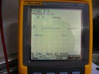
Here I show the pictures of each group of five fets.
The first corresponds to the first group (Q404,405,410,430,434)
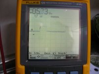
The second to the second group (Q411,412,413,414,431)
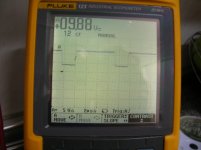
The third to the third group (Q426,427,428,429,433)
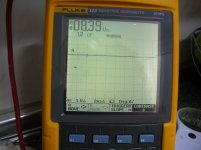
And the fourth to fourth group (Q417,418,419,420,432)
I have to indicate, in this latter group, the square waveform appears for a second, then disappears.
Here I show the pictures of each group of five fets.
The first corresponds to the first group (Q404,405,410,430,434)
The second to the second group (Q411,412,413,414,431)
The third to the third group (Q426,427,428,429,433)
And the fourth to fourth group (Q417,418,419,420,432)
I have to indicate, in this latter group, the square waveform appears for a second, then disappears.
Attachments
Well, I have not had much time for this amp, but now I'm back.
Perry, I have reviewed and reviewed several components, and I have not found anything strange.
The only thing I have noticed is that by changing the coupling of the oscilloscope to AC, the square waveform is shown in the four groups of five FETs of audio output.
Can this be relevant?
Perry, I have reviewed and reviewed several components, and I have not found anything strange.
The only thing I have noticed is that by changing the coupling of the oscilloscope to AC, the square waveform is shown in the four groups of five FETs of audio output.
Can this be relevant?
Hi, again I have returned to this amplifier that I have forgotten for some time ..
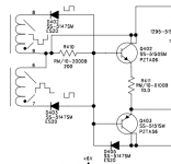
Well, before installing all the FET of the output stage, I have checked several points of the circuit and I have noticed, that I have a short between the ground and the drain of Q411, 412, 413, 414, 431, I have checked many points in the area but I have not found anything suspicious, any ideas?
Well, before installing all the FET of the output stage, I have checked several points of the circuit and I have noticed, that I have a short between the ground and the drain of Q411, 412, 413, 414, 431, I have checked many points in the area but I have not found anything suspicious, any ideas?
It seems that this short at this point, is normal.
I have installed all the output FETs, I connected the voltage, and the voltage of the rail that I get with respect to the ground of the amplifier is: - 61 v HV- red wire and + 31 v HV+ blue wire.
Tension between red and blue is: 93 v
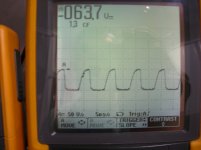
With the oscilloscope I get a non-perfect square waveform on the FET pins.
On the speaker output terminals: 0.036v
What do you think, Perry?
Can I install the diode I removed from the power supply? (D11)
I have installed all the output FETs, I connected the voltage, and the voltage of the rail that I get with respect to the ground of the amplifier is: - 61 v HV- red wire and + 31 v HV+ blue wire.
Tension between red and blue is: 93 v
With the oscilloscope I get a non-perfect square waveform on the FET pins.
On the speaker output terminals: 0.036v
What do you think, Perry?
Can I install the diode I removed from the power supply? (D11)
All right, Perry.
The scope has battery.
The probe ground is connected to the ground of the amplifier.
All FETS are the same.
The sample of the photo in particular is: Q413
In the speaker, (with audio sound in the rcas input) only a long and annoying long sound is heard,no clean audio
The scope has battery.
The probe ground is connected to the ground of the amplifier.
All FETS are the same.
The sample of the photo in particular is: Q413
In the speaker, (with audio sound in the rcas input) only a long and annoying long sound is heard,no clean audio
It's virtually impossible for all of the drive circuits to have the same exact fault resulting in the same defective waveform. This is likely perfectly normal.
If the scope is battery powered and has no connections to it other than the two probes, you can touch the probes to the gate and source to get a direct view of the drive waveform.
The audible noise is likely a preamp issue. I'd suspect a switch, bad shield ground or a bad crossover pot.
If the scope is battery powered and has no connections to it other than the two probes, you can touch the probes to the gate and source to get a direct view of the drive waveform.
The audible noise is likely a preamp issue. I'd suspect a switch, bad shield ground or a bad crossover pot.
- Status
- This old topic is closed. If you want to reopen this topic, contact a moderator using the "Report Post" button.
- Home
- General Interest
- Car Audio
- rockford fosgate t40001bd