Of course the TL494 can drive MOSFET directly without driving-transistors. That application can be found in older Harman car amplifiers (JBL and Concord white series) . Here the TL494 drives up to 6 IRF540N directly.
But small driving-transistors are recommended , if one or more of the MOSFET fail and cause a short, the TL494 will be saved if driving-transistors are being used.
Amplifiers made in Asia often use the 2SA1266 or 2SA1015 transistors for driving the MOSFET. Those are standard transistors as a BC557 is in Germany.
The more stable version of the TL494 is the TL594 , often used in Hifonics amplifiers series 8 .
Price changes with the manufacturer. The Texas Instruiments TL494 will def. be more expensive than a korean KIA494 , overhere the TL is sold for 50cents.
Greets
sdoom
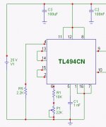
Here is a small SMPS with a TL494, used for a 250W RMS amplifier (korea-standard) .
Maybe this helps.
TL494_DC_converter
Maybe this helps.
TL494_DC_converter

Project report:
finally ,after many months of waiting and sourcing parts, my SMPS works:
1> chip used was SG3525.. simple oscillator mode with softstart only
no voltage regulator using the 4N35 optoisolator
2> diodes used were 200V 3A (R30D) could not find any high power rated in our area, got these from faulty PC Power supply
3> mosfets used: total of 4 IRFZ44 (2 per side) mounted on small heatsink
4> core used U-U core (from TV flyback transformer)<thick ones, not the slim> , or big E-I core or toriod, very rare to find
5> output cap used : 4,700uF/50V per side
6> softstart value of cap used: 4.7uF instead of 33uF
i turned the power on, after about 1/4 second, i hear a "sssssssssssssst"!!! but sound extinguished after 1/8sec.... twas the SMPS powering up and charging the 4,700uF...")
output was around 37V per side.... when i was using 1A regulated 12V but when i used a PC AT power supply(12V@8A), output was 51V.. under no load.... so, i think ill put/add voltage sensing using 4N35, but i think that would make the SMPS efficient enough?? comments pls...
---==== NOW TESTING TIME ====----
amp used 100W rms amp , published in our local country... supply was +40,gnd,40 @4A... i used this amp as my subwoofer amp... connected to my PC through an active sub filter... I first tried the 1amp 12V supply, for safety sake... all went well, until you put it to full power(amp)... sound output is moderate... and i hear a "ssssssssssst" every second or two, on full sound output!! well its understandable because my 12V power supply cant supply the current demand!!
i was still afraid to use the 12V 8A PC PC because my SMPs still got no voltage sensing circuit.. maybe it will blow my amp.. maximum supply valtage must be under 100V... still gonna add it, sensing circuitry.... the other thing im worried about are the fast recovery rectifier diodes (R30D).. looks like 1N5401.... thay arent mounted on heatsinks like the BYw diodes.... i cant source them locally....
anyway, my SMPS works... no heating of SMPS parts .. just my 12V 1A power supply.. hehehehe
btw, SG3525 is way much better and easier to use than TL494.. but it could be done... need more time though....
thats all for now.....
finally ,after many months of waiting and sourcing parts, my SMPS works:
1> chip used was SG3525.. simple oscillator mode with softstart only
no voltage regulator using the 4N35 optoisolator
2> diodes used were 200V 3A (R30D) could not find any high power rated in our area, got these from faulty PC Power supply
3> mosfets used: total of 4 IRFZ44 (2 per side) mounted on small heatsink
4> core used U-U core (from TV flyback transformer)<thick ones, not the slim> , or big E-I core or toriod, very rare to find
5> output cap used : 4,700uF/50V per side
6> softstart value of cap used: 4.7uF instead of 33uF
i turned the power on, after about 1/4 second, i hear a "sssssssssssssst"!!! but sound extinguished after 1/8sec.... twas the SMPS powering up and charging the 4,700uF...
output was around 37V per side.... when i was using 1A regulated 12V but when i used a PC AT power supply(12V@8A), output was 51V.. under no load.... so, i think ill put/add voltage sensing using 4N35, but i think that would make the SMPS efficient enough??
comments pls...---==== NOW TESTING TIME ====----
amp used 100W rms amp , published in our local country... supply was +40,gnd,40 @4A... i used this amp as my subwoofer amp... connected to my PC through an active sub filter... I first tried the 1amp 12V supply, for safety sake... all went well, until you put it to full power(amp)... sound output is moderate... and i hear a "ssssssssssst" every second or two, on full sound output!! well its understandable because my 12V power supply cant supply the current demand!!
i was still afraid to use the 12V 8A PC PC because my SMPs still got no voltage sensing circuit.. maybe it will blow my amp.. maximum supply valtage must be under 100V... still gonna add it, sensing circuitry....
the other thing im worried about are the fast recovery rectifier diodes (R30D).. looks like 1N5401.... thay arent mounted on heatsinks like the BYw diodes.... i cant source them locally....anyway, my SMPS works... no heating of SMPS parts .. just my 12V 1A power supply.. hehehehe
btw, SG3525 is way much better and easier to use than TL494..
but it could be done... need more time though.... thats all for now.....
4 turns pri, 12 turns sec...
I think a bigger U-U core and larger filer caps(2 x 4,700uF) per side....
ive connected my AMP.. but before i did connect, ive read the article if it can handle supply of 100V DC.... it did not mention, so ive scanned for the trannies used... almost all where rated at 100V... only 2 were not.... 40V for the short circuit portection( but its hardly ever used)....
result??? all went fine with PC AT supply (12V @ 8A)...
but i think the SMPS can ONLY??? supply 3A at best (due to 3A fast rectifier used).... anyways, no heating of SMPS components(even the diodes......
so i think im not gonna add the 4N35 opto cause my AMP can handle the extra votage output...
I think a bigger U-U core and larger filer caps(2 x 4,700uF) per side....
ive connected my AMP.. but before i did connect, ive read the article if it can handle supply of 100V DC.... it did not mention, so ive scanned for the trannies used... almost all where rated at 100V...
only 2 were not.... 40V for the short circuit portection( but its hardly ever used)....result??? all went fine with PC AT supply (12V @ 8A)...
but i think the SMPS can ONLY??? supply 3A at best (due to 3A fast rectifier used).... anyways, no heating of SMPS components(even the diodes
...... so i think im not gonna add the 4N35 opto
cause my AMP can handle the extra votage output... RX5 said:Project report:
finally ,after many months of waiting and sourcing parts, my SMPS works:
1> chip used was SG3525.. simple oscillator mode with softstart only
no voltage regulator using the 4N35 optoisolator
2> diodes used were 200V 3A (R30D) could not find any high power rated in our area, got these from faulty PC Power supply
3> mosfets used: total of 4 IRFZ44 (2 per side) mounted on small heatsink
4> core used U-U core (from TV flyback transformer)<thick ones, not the slim> , or big E-I core or toriod, very rare to find
5> output cap used : 4,700uF/50V per side
6> softstart value of cap used: 4.7uF instead of 33uF
i turned the power on, after about 1/4 second, i hear a "sssssssssssssst"!!! but sound extinguished after 1/8sec.... twas the SMPS powering up and charging the 4,700uF...
output was around 37V per side.... when i was using 1A regulated 12V but when i used a PC AT power supply(12V@8A), output was 51V.. under no load.... so, i think ill put/add voltage sensing using 4N35, but i think that would make the SMPS efficient enough??
---==== NOW TESTING TIME ====----
amp used 100W rms amp , published in our local country... supply was +40,gnd,40 @4A... i used this amp as my subwoofer amp... connected to my PC through an active sub filter... I first tried the 1amp 12V supply, for safety sake... all went well, until you put it to full power(amp)... sound output is moderate... and i hear a "ssssssssssst" every second or two, on full sound output!! well its understandable because my 12V power supply cant supply the current demand!!
i was still afraid to use the 12V 8A PC PC because my SMPs still got no voltage sensing circuit.. maybe it will blow my amp.. maximum supply valtage must be under 100V... still gonna add it, sensing circuitry....
anyway, my SMPS works... no heating of SMPS parts .. just my 12V 1A power supply.. hehehehe
btw, SG3525 is way much better and easier to use than TL494..
thats all for now.....
It sounds like you're making some good progress. If you do not absolutely need an isolated output you could add regulation to your circuit by doing these things:
1. Put a reference voltage on pin 2 of the controller chip [1k resistor from pin 16 - pin 2, and a 1k from pin 2 to ground]
2. Link the ground from your output to your supply ground with a 10k resistor
3. The reference voltage will be 2.5v, so if you would like a regulated 45v supply, you need approximately a 20k resistor from your positive output to pin 1 of the '3525, and a 1k resistor from pin 1 to ground. This ratio just sets the output voltage, I just guessed in my head. It is a voltage divider with Vin = 45v and Vout = 2.5v
4. If you do this you must add an output inductor! You mentioned getting some parts from burned up PC power supplies. The big yellow core in those is excellent for an output inductor. Wind both your positive and negative leads on that toroid before the capacitors.
I'm not sure if you mentioned your switching frequency, but anyway you should try to get about 10 wraps on this output inductor if possible.
Your controller is capable of good regulation, let us know if you try it out.
==================================raidfibre said:
It sounds like you're making some good progress. If you do not absolutely need an isolated output you could add regulation to your circuit by doing these things:
1. Put a reference voltage on pin 2 of the controller chip [1k resistor from pin 16 - pin 2, and a 1k from pin 2 to ground]
2. Link the ground from your output to your supply ground with a 10k resistor
3. The reference voltage will be 2.5v, so if you would like a regulated 45v supply, you need approximately a 20k resistor from your positive output to pin 1 of the '3525, and a 1k resistor from pin 1 to ground. This ratio just sets the output voltage, I just guessed in my head. It is a voltage divider with Vin = 45v and Vout = 2.5v
4. If you do this you must add an output inductor! You mentioned getting some parts from burned up PC power supplies. The big yellow core in those is excellent for an output inductor. Wind both your positive and negative leads on that toroid before the capacitors.
I'm not sure if you mentioned your switching frequency, but anyway you should try to get about 10 wraps on this output inductor if possible.
Your controller is capable of good regulation, let us know if you try it out.
for #1, i will try to consider
#2, well nice way of tying those GND's....
how did you come up with this idea?? experience??? nice TIP #4, i have an output inductor, i used a TOROID iron core(i think thats it??
abotu 1 inch in outer diameter i forgot how many turns i made( but what i was after was that the magnet wire would entirely cover the area of th toriod... done both windings on that toroid. for the freq, i used 3.3K and 10K trim in series for "R" and .0047uF for "C"... for me i used the 10K trim to "tune" the output voltage...
to be effecient i hope... lower freq means lower voltage output and "too high" a frequency would be just the same as a lower freq, output is low... i think its because i never used a ferrite toroid for the main switching transformer.... (remember i used U-U core from flyback)... anyways, imm happy it worked 1st time and no parts where wasted... and this proves that we could make SMPS even without using ferrite toroid core, even U-U cores can be done.. as long as the material is ferrite... havent used an E-I core, because i could not source it out locally.....

djQUAN
i got no scope
maybe ill try your proposition on using 6T on the pri... guess i w will have to wind it again
but still, i get no heating on the SMPS... the only one that heats is my AMP
btw, Where did you get your toroid? mail order? from where? how much?
and what rect diode did you use??
i got no scope
maybe ill try your proposition on using 6T on the pri... guess i w will have to wind it again
but still, i get no heating on the SMPS... the only one that heats is my AMP
btw, Where did you get your toroid? mail order? from where? how much?
and what rect diode did you use??
I bought my toroids from raon (small ones, 40pesos) and from hongkong (really big ones, still have a few left, forgot the price) in my last visit last april.
when I use less than 6 turns on the primary, I get ringing, large spikes, and heating of the power MOSFETs.
for the rectifiers, I think I used MUR1620 ??? all I know is it's a TO-220 device, dual diodes. 16A 200V.
each device is paralleled so I have 32A , using four per SMPS.
do you still want my TL494 circuit? you still have to wait though, I have to scan it at my friend's house.
djQUAN said:I was able to get my power MOSFETS (95A and 110A devices) and the rectifiers on a sidewalk vendor brand new for 10pesos each.
email is djquan128@hotmail, same username on yahoo (but I check the hotmail more often)
raon is in manila, near chinatown.
at that price?? SO SO cheap hehehe
wish i was there :Ive rewound the ferrite transformer again(as compared to my 4T+4T and 12T+12T).... 6T + 6T primary and 23T + 23T(i should have made it 24T or 25T instead!! )... used #26 in 7 strands(for primary) parallelled together to form 1 solid wire( using VISE and electric drill to "twist" them) ive found this on the NET, they call it the "litz" wire.....the secondary was 3 parrallel strands of #20 magnet wire.......voltage output now was at 45V per side(no more overvoltage compared to my first rewind).... it REALLY helps when you "tidy up your wiring"... my rewinding style was like rewinding a TOROID ferrite, where you just continue in one direction until you come up with the right turns... even though my core was a U-U core....
--===== SOUND???? ====-----
well, AMP sounds really better now....I get MORE power and still no heating of SMPS.. the only thing that heats up is my AMP!!!
even at full power, SMPS is still cool to the touch... the fact that i used a small heatsink for the MOSFETs.....btw, is paralleling 2 3amp diodes equal to a single 6amp doide??
- Status
- This old topic is closed. If you want to reopen this topic, contact a moderator using the "Report Post" button.
- Home
- General Interest
- Car Audio
- car smps based on TL494