Had typical shorted outputs and blown ps.Amp has tester ps and output mosfets installed.Uses irfp250N as outputs.
Replaced what I believe was ir21844s on output card as driver.Various pin locations matched up correctly.
Amp seems to be cycling quickly (quicker than the protect light will flash it seems) on dc offset.As it tries to start oscillating a quick 1-2vdc appears at speaker terminals and cycle repeats.
Pulled one side of output inductor(large one) and it measured ~50uh with my not the greatest inductance meter that needs updated.
With the one side of the inductor(technically the output side of the inductor) removed the outputs will oscillate R-R.But if I reconnect it it goes back to short cycling.
Can scoping the output of the inductor tell me anything useful?
Anyone have definitive measurements of the output chokes?
FYI-The 10ohm resistor from the input of the inductor to Vs on driver chip was completely open as well with the tvs(pk6?) was practically shorted causing full negative rail at speaker terminal.
I'm assuming that with finding that resistor and tvs faulty.That there's an inductor issue that started the whole down fall.
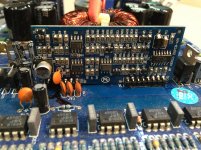
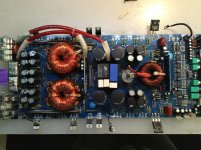
Attachments
If you use a large 50-100w 2 ohm resistors (or anything similar) between the inductor winding and the board were it was connected, does that change the behavior of the amp?
For the following, you need to drive audio into the amp. A sine wave of about 50-100Hz if possible.
If you bridge pins 2 and 3 if the 21844 and connect a 10k resistor between pins 1 and 2 of the TL072 on the driver board, do you get clean audio on pin 1?
Do you get a square wave that swings between the 5v rails on pin 7 of the LM211?
Do you get a 10v square wave swinging from the negative rail to about 10v above the negative rail on pin 1 of the 21844?
Well the lack of oscillation was caused by gain pot turned all the way down.Either driving a signal in or making a connection across speaker terminals with start oscillation.
Got a problem.The high side outputs get overly hot in just a few seconds.The amplitude of drive and signal look okay.Ive tried many different outputs(640,4229,4332,264n,250N) original part # included and the idle current amongst them all is fairly close but they all get hotter than I'm comfortable with and leaving in just 10-15 seconds.Im not sure if it's a cross conduction issue or what.
I've checked the dead time resistor off pin 4 of 21844.The diode and bootstrap cap have been removed and checked and even replaced.
Perhaps this thing has some bad engineering?Better odds are I missed something.
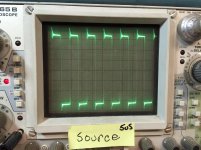
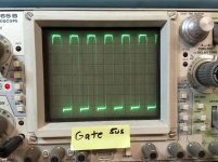
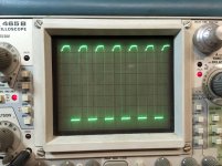
To follow will be gate and source photos from high side with inductor installed just to clarify.
Got a problem.The high side outputs get overly hot in just a few seconds.The amplitude of drive and signal look okay.Ive tried many different outputs(640,4229,4332,264n,250N) original part # included and the idle current amongst them all is fairly close but they all get hotter than I'm comfortable with and leaving in just 10-15 seconds.Im not sure if it's a cross conduction issue or what.
I've checked the dead time resistor off pin 4 of 21844.The diode and bootstrap cap have been removed and checked and even replaced.
Perhaps this thing has some bad engineering?Better odds are I missed something.
To follow will be gate and source photos from high side with inductor installed just to clarify.
Still working on the ringing a little bit.Have made some progress I believe.Added some 1n4148 diodes reverse across the gate resistors.Idle current came down ~500 mA which is huge and the outputs barely get warm after 30 seconds.
It appears the falling edge of the waveform is closer to vertical now than before.
Doing a little more testing and I'll post back.Currently using irf640n's for testing.Hopefully one of the other preferred choices reduces idle current more and I can put a load on this thing.
It appears the falling edge of the waveform is closer to vertical now than before.
Doing a little more testing and I'll post back.Currently using irf640n's for testing.Hopefully one of the other preferred choices reduces idle current more and I can put a load on this thing.
Irfp4227,changed pull down configuration a little and it is now 10K vs the 25k it had.Added uf4007's in reverse across gate resistors.
Signal looks pretty good I think.Takes about a minute now before the outputs get too hot to be comfortable.
Anyone see this design amp before?The audio driver board just says MC1200?
Customer did state that at practical idle,heatsink temp would be higher than "normal".
Either I missed a problem that it still has or it was poorly designed and I might of improved it?lol...
How do you determine as far as calculations and whatnot,maximum amount of mosfets a driver can handle?
If you ad 2 transistors at a time(1 high 1 low) until you have 6 installed total.You can practically measure the time it takes for the outputs to reach a certain temp as you keep installing more.At 6 installed,it will idle practically indefinitely without overheating any of the high side outputs.,Although they will warm up some,quicker than with 4 installed.
Install the last two(total of 8) and if left too long,it will Avalanche and short a couple.
It seems to be okay now (good enough)that I've made some changes.
Is it possible that 1 ir21844s can't drive 8 mosfets without a buffer stage correctly?Original fets were irfp250N.I haven't quite figured out how to do those calculations yet.
I don't know about the calculations. Generally Qg is the determining factor for output FETs in class D circuits. Lower Qg means that they are easier to drive. That doesn't, however, mean that that's the only important specification/parameter when trying to find substitute FETs that will work in various amps.
Adding the parallel diodes may make it run cooler but will add to the stress on the IC. Increasing deadtime (pulldown in a previous post?) will help prevent cross conduction and won't stress the IC.
Adding the parallel diodes may make it run cooler but will add to the stress on the IC. Increasing deadtime (pulldown in a previous post?) will help prevent cross conduction and won't stress the IC.
Well,it seems to working like a champ.Ran it for ~1hour twice at full load(even to the point where it tripped over current a couple times) with no issues.
Just so it's clear in case someone ends up in this same boat.
I put the original gate and pull down resistors back in(47RGate,100kPD) and all 8 outputs(I used irfb4227.Got to spread the the legs a little bit and whatnot to get them to fit)
Irfb4227 drew the least amount of idle current and ran the coolest.
Amp would draw 2.2 amps of current at idle.Also random outputs would overheat in seconds.
Installed uf4007 diodes reverse across every gate resistor and idle current dropped to 1.7 and it would sit for minutes outside of heatsink and no outputs got over 90 degreesF.
Glued a small heat sink to ir21844s driver as well because it got hotter than I felt comfortable with.
I'm not sure why it ran lousy in general as far as the output temps are concerned but the reverse diodes made a HUGE improvement.
Perry mentioned that it may stress the driver a little more.Im not sure how hot it ran previously but it's hot now.The heat sink helped a lot.
I've beat on it with a resistive load for hours and all is well.
- Status
- This old topic is closed. If you want to reopen this topic, contact a moderator using the "Report Post" button.
- Home
- General Interest
- Car Audio
- Hifonics brx2000D