Trying to repair the sub channel on a Rockford Fosgate Power 600.5 and am having some difficulties with different voltages on the left and right sides of the sub channel. The four channel section has no issues, the power supply has already been repaired with IRF3205 transistors. Amp plays fine on the four channels with the sub outputs removed. Does anyone have a schematic for this amp? All the schematics that I have downloaded are for the Punch 600.5 which uses IRF540/9540 in the sub channel. I need the schematic for the Class G sub channel with IRF9Z34, IRF5210, IRF540, IRF1010E transistors in the output section. Thanks.
The only schematic that I was able to find is named 600a5 _PC-1986-E.pdf. In this schematic the PS FETs are SSP60N06 while my amp came with IRF1010E in the power supply.
The PC # on my amp is PC-3296-D.
The power supply FETs may have been changed when the series went from a5 to .5 and I understand their similarity, but does that mean the sub channel of my 600.5 can be rebuilt using 2 IRF540s and 2 IRF9540s instead of the IRF9Z34, IRF5210, IRF540, and IRF1010E that it originally came with?
I have managed to destroy one of the smd transistors/diodes that has A7 marked on it. What component is that?
Well, I guess the circuit schematic and component locations are the same.
It seems that D10 which I destroyed is a BAV99LT, is there an equivalent through-hole replacement for this component that I may have or can get locally? I have some smd diodes from JL amps if those will work...
It seems that D10 which I destroyed is a BAV99LT, is there an equivalent through-hole replacement for this component that I may have or can get locally? I have some smd diodes from JL amps if those will work...
So I scavenged an smd diode marked A7 from a spare circuit board, it reads the same as the originals and is functioning. I still have differing voltages on either side of my sub channel. I don't know much about Class G, so I will post some of the voltage readings at some locations in the channel. I am not sure how these outputs are driven so I don't know what voltages to look for on the pads for the outputs or in the channels. I know something is still not right and hoping to catch it before putting in the outputs and damaging them.
READINGS AT SUB CHANNEL OUTPUTS (Black probe on B-)
Q522 52.5 27.1 53.2 (IRF9Z34)
Q510 10.5 0.00 27.1 (IRF5210)
Q511 -11.1 0.00 -27.0 (IRF540)
Q521 -50.6 -27.0 -52.3 (IRF1010E)
READINGS AT DIODES, RESISTORS, AND TLO72C (Black probe on B-)
Positive Half of Channel
R565 52.4 to 43.1
D505 42.5 43.1 43.1
U503:
1) 23.4
2) 43.0
3) 42.4
4) 21.2
5) 34.6
6) 27.2
7) 51.1
8) 52.4
Negative Half of Channel
R577 -51.9 to -31.3
D10 -30.7 -31.3 -31.3
U504
1) -22.1
2) -31.3
3) -30.7
4) -51.9
5) -28.7
6) -25.1
7) -50.1
8) -20.8
U502
1) 13.6
2) 0.4
3) 3.3
4) -12.6
5) -3.3
6) 0.4
7) -11.5
8) 14.0
This amp is different only in the fact that it has 2 rail voltages. It operates from the lower rails until the output level requires more voltage. Then the higher rails are driven to the outputs.
You can't generally use the voltage on the output transistors with the output transistors out of the circuit. Install the outputs. Set the bias fully counter-clockwise. Clamp the FETs to the heatsink and power up through a current limiter. That will minimize the risk to the outputs.
You can't generally use the voltage on the output transistors with the output transistors out of the circuit. Install the outputs. Set the bias fully counter-clockwise. Clamp the FETs to the heatsink and power up through a current limiter. That will minimize the risk to the outputs.
So, which one is correct, A or B?
A) The +-28v that exists in the sub channel is actually coming from the same regulators (+-28v) as channels 1-4 but will draw from the second (+-50v) when additional voltage is demanded?
B) Is the +-28v in the sub channel actually coming from the second pair of regulators (+-50v) and being created in the channel itself from the +-50v?
Installed Q510 (IRF5210) and Q511 (IRF540) and the amp produces clean audio. It does seem a little low volume at this point in time, but if the gain is turned up, it has a little bump to it, even with just those two outputs installed.
CURRENT READINGS AT SUB CHANNEL OUTPUTS (Black probe on B-)
Q522 52.1 28.1 53.4 (IRF9Z34 not installed)
Q510 26.5 0.00 28.0 (IRF5210 installed)
Q511 -25.3 0.00 -28.0 (IRF540 installed)
Q521 -51.4 -28.0 -53.2 (IRF1010E not installed)
What next? Is it safe to install Q522 and Q521?
CURRENT READINGS AT SUB CHANNEL OUTPUTS (Black probe on B-)
Q522 52.1 28.1 53.4 (IRF9Z34 not installed)
Q510 26.5 0.00 28.0 (IRF5210 installed)
Q511 -25.3 0.00 -28.0 (IRF540 installed)
Q521 -51.4 -28.0 -53.2 (IRF1010E not installed)
What next? Is it safe to install Q522 and Q521?
You can install Q521/522.
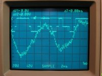
Make a note of the amplitude where you just start to see clipping (without 521/522). Install Q521/522. At the point where you saw that amp just start to clip previously, you should see the rail voltage increase on the output transistors on musical peaks. If that's what you see for the positive and negative rails, the amp is switching correctly. The attached photo is from an amp with a 3-stage rail but you should see something similar. The image shows the positive rail on one channel and the audio signal on the other channel.
Make a note of the amplitude where you just start to see clipping (without 521/522). Install Q521/522. At the point where you saw that amp just start to clip previously, you should see the rail voltage increase on the output transistors on musical peaks. If that's what you see for the positive and negative rails, the amp is switching correctly. The attached photo is from an amp with a 3-stage rail but you should see something similar. The image shows the positive rail on one channel and the audio signal on the other channel.
Attachments
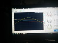
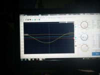
Are these pics an example of the HV rail switching into the LV rail?
The blue line is channel 1 connected to the source of the positive output, while the yellow line is channel 2 connected to the drain of the positive output.
The blue line is channel 1 connected to the source of the positive output, while the yellow line is channel 2 connected to the drain of the positive output.
Attachments

- Status
- This old topic is closed. If you want to reopen this topic, contact a moderator using the "Report Post" button.
- Home
- General Interest
- Car Audio
- Need schematic for RF Power 600.5 / Punch 600a5