Is this the high side or the low side?
If this is the high side and you're absolutely sure that there is no secondary voltage, jump the high-side source leg to the secondary ground. You can use a low value (1-10 ohms, 1/4w resistor) if you want to offer a bit of protection in case there are other problems.
If this is the high side and you're absolutely sure that there is no secondary voltage, jump the high-side source leg to the secondary ground. You can use a low value (1-10 ohms, 1/4w resistor) if you want to offer a bit of protection in case there are other problems.
So i scoped it again.
Scope settings: ground from the amplifier GND terminal, probe 1X
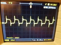
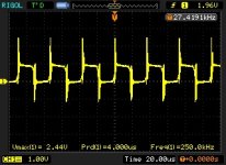
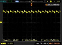
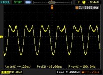
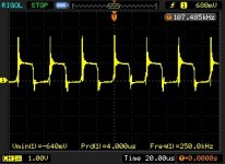
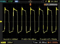
Gate measurements.
First picture from the banks which is closer to rectifiers, should be high side,
the second one is from the low-side.
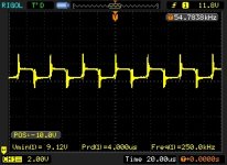
Third picture is also low side, BUT vertical position of the scope is -10.0V
Scope settings: ground from the amplifier GND terminal, probe 1X
Gate measurements.
First picture from the banks which is closer to rectifiers, should be high side,
the second one is from the low-side.
Third picture is also low side, BUT vertical position of the scope is -10.0V
Attachments
Last edited:
Here is what i have on driverboard input, its not cliped, because its driven to hard, its just whats comes in on board. From rca its clean signal.
Another thing. If i ground scope probe on secondary ground (speaker output minus terminal), i dont see any oscillation signal on gates from output transistors.
Second picture. About grounding source leg, transistors are not grounded yet, here is signal on all output transistors source legs (amplifier main ground terminal as reference)
Attachments
Last edited:
Sorry that again i didnt mention grounding.
Picture before was grounded on secondary ground.
Here is the picture when probe is on amplifier main ground (the same input pin on drivercard). If i drive sinus signal in amp, i see that signal is oscillating in driven frequency.
Both measurements done when driver board is out of main board, because i have problem to probe while its in. Should i measure while its in?
Attachments
Last edited:
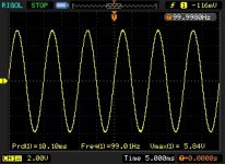
I started to rembember that before i removed rectifiers I tested and had good sine wave from pre-amp board.
Here what i have done:
Removed all output transistors. Reinstalled rectifiers.
And this is the input at driverboard (drivercard is removed), clean sinewave signal. I just removed outputs and reinstalled rectifiers.
Edit. While outputs are out of board, i now tested the drive signal, low-side gate drive is the same as before, high side i didnt check, because i did not install the 9v battery for 21844.
Attachments
Last edited:
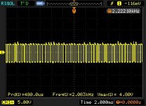
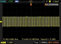
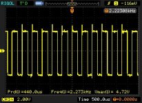
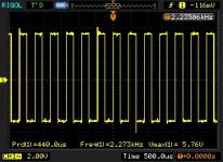
AC coupled. Scope ground on negative speaker terminal. high side with 9v battery.
First two pictures with 5V and 2ms settings, and last two with 2V and 500us.
1th and 3th is high side.
2th and 4th is low side.
First two pictures with 5V and 2ms settings, and last two with 2V and 500us.
1th and 3th is high side.
2th and 4th is low side.
Attachments
Last edited:
- Status
- This old topic is closed. If you want to reopen this topic, contact a moderator using the "Report Post" button.
- Home
- General Interest
- Car Audio
- Ground Zero 10kXSPL