hmm.. kind of "progress" here: when touching both R40 and R56 (100 Ohm SMD-resistors in parallel with close proximity) simultaneously with my finger, the current draw drops from 8 Amps to only 800mAmps which is normal i believe.
Oscillation wave at the output then also form to a perfect sine wave.
This only occours when touching the resistors with my finger and not when physical force is applied - hence no solder crack or else.
Not much of an scientific line of action, but I'm starting to believe the problem may originate from the opto coupler (6N137) circuitry.
Replaced both resistors + C30 and C74 (which stabilizes the VBB feed to the high-side gate drive transistors).
Strange thing is that the VBB-line (which also feed U8 (5V regulator)) starts off with 11VDC then drops slowly to beneath 10VDC.
5V out is OK though.
Will try replace the regulator tomorrow.
They all do!
Both low- and high-side gate drive signal smoothens out so that the "shaky bit" disappears to a firm square puls.
Same thing then happens to inductor input side.
Oscillation wave at speaker output terminal before was sine wave shaped, but with plenty of distortion. When touching the resistors mentioned above, sine wave also clears up and battery power consumption drops from 8A to 900mA.
Wondering what causes this..
Inductor output side is connected directly to a thick cable which runs towards speaker output terminal.
I did cut that cable.
Inductor measures 82μH on my LCR.
No difference in current draw.
All scope images stays the same too.
Only touching those resistors makes a difference.
Seems like my body somehow is absorbing that noise at the gate drivers.
I did cut that cable.
Inductor measures 82μH on my LCR.
No difference in current draw.
All scope images stays the same too.
Only touching those resistors makes a difference.
Seems like my body somehow is absorbing that noise at the gate drivers.
Output leg from L1 inductor is now free as a bird..
Amp still draws 8A when remote is applied.
Touching the resistors doesn't make the square wave into a sine wave, but the distorted square wave (at output FETs) become undistorted and idle current draw drops.
At speaker output terminal there is a sine wave (distorted). Touching the resistors makes the sine wave to go undistorted too.
Perhaps there is some ripple noise from unfiltered power lines.
Will try to heat up electrolytic caps with an air gun to see if anything changes.
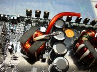
Attachments
Clean all solder pads to ensure that there are no bridges. Connect the side of the inductor that connects to the output FETs to the ground terminal of the amp.
Do you have a clean drive signal on the high and low FETs?
If so...
Load them with a small capacitor (0.01uf - not critical) between pads 1 and 3 (individually). Do you still have a clean drive signal of about 10v for all FETs?
Do you have a clean drive signal on the high and low FETs?
If so...
Load them with a small capacitor (0.01uf - not critical) between pads 1 and 3 (individually). Do you still have a clean drive signal of about 10v for all FETs?
FETs removed and pads cleaned.
Inductor input side connected to battery negative.
100% clean drive signal now at both low- and high side gates.
Removing battery negative side latch; low side still perfect, but high side completely messed up.
I'll try to add some capacitors now.
Inductor input side connected to battery negative.
100% clean drive signal now at both low- and high side gates.
Removing battery negative side latch; low side still perfect, but high side completely messed up.
I'll try to add some capacitors now.
Are the gate resistors within tolerance?
If so, follow the signal back to the emitters of the drivers, then to the bases of the drivers back to the output of the opto-coupler to see where you're losing the amplitude. Be careful on the opto, shorting the legs on the output side together will almost always destroy it.
If so, follow the signal back to the emitters of the drivers, then to the bases of the drivers back to the output of the opto-coupler to see where you're losing the amplitude. Be careful on the opto, shorting the legs on the output side together will almost always destroy it.
Thank you so far, Perry!
I will try to replace the drivers for high side once more, and also gate resistors.
Q11 and Q13 are the drivers and the fact that they both have in common R40 and R56 (which "smoothens out" the FETs at load when touched), makes me think they're at stake once more..
I'll get back
I will try to replace the drivers for high side once more, and also gate resistors.
Q11 and Q13 are the drivers and the fact that they both have in common R40 and R56 (which "smoothens out" the FETs at load when touched), makes me think they're at stake once more..
I'll get back
Did receive new driver transistors today.
I also ordered new original FETs: IRF 640N (<--- mind the N suffix).
Did only mount the new 640N's.
Well, it seems the FETs were the major culprit.
Amp now only draws 770mA at idle and works 100% perfect connected to subwoofer element.
All the previous IRF640's were brand new and of exactly the same batch with identical production numbers - they just didn't have the N-suffix.
Browsing the net (and even this site), it seems there are only minor differences between these two "models" of old and new IRF640's - yet evidently enough to cause a no night sleep..
I will replace all 4 gate driver transistors as well, but all scope images so far shows up as perfect.
Learned something new today, but thanks to Perry Babin once more for yet another informative guidance!")
I also ordered new original FETs: IRF 640N (<--- mind the N suffix).
Did only mount the new 640N's.
Well, it seems the FETs were the major culprit.
Amp now only draws 770mA at idle and works 100% perfect connected to subwoofer element.
All the previous IRF640's were brand new and of exactly the same batch with identical production numbers - they just didn't have the N-suffix.
Browsing the net (and even this site), it seems there are only minor differences between these two "models" of old and new IRF640's - yet evidently enough to cause a no night sleep..
I will replace all 4 gate driver transistors as well, but all scope images so far shows up as perfect.
Learned something new today, but thanks to Perry Babin once more for yet another informative guidance!
Attachments
Well, I do not know but they made the difference. Perhaps the Earthquake Mini D2000 is designed extremely "finetuned" to these particually components. After all they figure in the scheme - and their "a/d-module" is entirely encrypted . Who knows. Electrons move fast..
Thanks again though!
Thanks again though!
- Status
- This old topic is closed. If you want to reopen this topic, contact a moderator using the "Report Post" button.
- Home
- General Interest
- Car Audio
- Earthquake Mini D2000 idles at 8 Amps