The amplifier is a Powerbass XTA4000, it came to me with blown power supply MOSFETs, drivers, and gate resistors. I replaced all of those, now the power supply comes up fine. There is still no output from the amp, the gates on the FETs aren't switching. The driver board is marked DWM3640NHV_V30, the ICs are ground off. From the tracing I did on the board, the MOSFET drivers appear to be pin compatible with IR21844S, guessing the opamp is a TL072, and the comparator I'm really not sure of the part number on the comparator, guessing LM393 or 211, not sure what would make one compatible and the other not... but since I have a good square wave output from it, not very concerned at this point. The signal at the IR21844S-s inputs referenced to VSS is a good square wave, nothing on either HO or LO, referenced to their appropriate points. I went ahead and replaced (what I thought were) the IR21844S and still nothing. After all of the poking around I have done, the only idea I have is that the SD pin isn't being pulled high enough to enable the outputs, or I damaged both of the ICs while soldering them on. I read that they can handle 300ºC for 10 seconds while soldering, so I set my iron at 300 C and didn't keep the iron on the pins for longer than 10 seconds. I gave plenty of time to cool down between stabs with the iron, a few minutes each smoking half of a cigarette between stabs.
When I put the scope (Hantek 6022BE USB scope) the scope trace freezes on the laptop, which I've never seen before. I don't have the tektronix 561B at the shop right now, or I would have been using that. When I put the multimeter on it, it showed 0.5xx V between SD (small tangent, but the line over the SD in the datasheet means NOT right? like in a differential signal, you have A and A(not) right?) and VSS. All I see in the datasheet is that it's a logic level input. I can't find any info as to what the voltage needs to be to be considered logic high.
So what I'm looking for, is if anyone knows what the SD pin needs to be pulled up to in order to enable the outputs, or any other suggestions what to check. Would it be safe to throw an lm7805 onto a battery and apply 5v to the SD pins, just to see what it does to the outputs on the IR21844Ss?
By the way, all linear regulators on the main board are outputting fine. I haven't pulled the board from the heatsink yet to trace where the SD pins are driven from. Audio is passing through the preamp fine, and as I said the opamp and comparator appear to be functioning fine.
I apologize for this post being rather long winded, I want to be as thorough on the information I provide as I can, and at this point I'm feeling a bit flustered. I sincerely thank you all for reading all of this, and for any input you may have. I look forward to seeing what you all have to say.
-Jimmy
After further reading in the IR21844 datasheet, I have found
VSD,TH+ SD input positive going threshold min 2.7V
VSD,TH-SD input negative going threshold max 0.8V
So the SD definitely isn't being brought up, and I probably senselessly replaced the ICs on the driver. I'll pursue the source of the SD signal further on Monday when I'm back in the shop.
VSD,TH+ SD input positive going threshold min 2.7V
VSD,TH-SD input negative going threshold max 0.8V
So the SD definitely isn't being brought up, and I probably senselessly replaced the ICs on the driver. I'll pursue the source of the SD signal further on Monday when I'm back in the shop.
IRS21844S or IR21844S
TL072
LM211
The SD pins are internally pulled up. They are pulled down by the protection circuit. Pins 6 and 16 can pull down from the main board. Transistors 6 and 8 pull down in conjunction with the LM393 on the driver board.
Disabling the protection circuit is sometimes safe to aid in troubleshooting but I wouldn't advise it here. If there is a true over-current fault, it could blow the outputs and the driver ICs if the protection is defeated.
amp is idling around 2.5 amps, my DC clamp is kindof slow, I don't have an analog hooked up with a shunt, but I don't see any spike in current as if it's hitting an over current state. And I havn't seen a single pulse on the scope when on the gates of the output FETs. Also makes me question an over current state.
Would that protection be coming from the power supply? or do you have any suggestions what to look at, why the pin is being pulled down?
Would that protection be coming from the power supply? or do you have any suggestions what to look at, why the pin is being pulled down?
An over-current fault won't necessarily cause a noticeable draw from the 12v source because the reaction by the protection circuit is so quick and the energy is taken from the charged rail caps.
First, you need to determine if the pulldown is coming from the main board or the comparator on the driver board.
First, you need to determine if the pulldown is coming from the main board or the comparator on the driver board.
I will pursue that information as soon as I get in the shop Monday.
If the comparator on the driver board is pulling it down, why would it normally do so?
And if the main board is pulling down, why would it normally choose to do so? Something from the tl494?
Thanks so much for the help. I'm trying to get as much info as I can before I go back at it.
If the comparator on the driver board is pulling it down, why would it normally do so?
And if the main board is pulling down, why would it normally choose to do so? Something from the tl494?
Thanks so much for the help. I'm trying to get as much info as I can before I go back at it.
I'm not familiar with this amp but for similar amps...
If the comparator is shutting it down, it's likely overcurrent.
If the problem is in the main board, it's likely a defective transistor.
There are a few amps that have additional over-current protection on the main board but I don't know if that applies to this amp.
Have you tried to get a diagram from the manufacturer?
I have not tried the manufacturer for a schematic. I figure if they grind off the part numbers, why would they be helpful to someone other than their people working on one of their amps. But I will see how that works out.
I'm curious where it's over-current information would be coming from. I don't see any obvious shunts or current transformers. Either way, tomorrow I'll see if I can track down where it's pulling down from and try to take it from there.
Thanks again for all of the help. Hopefully the day away from it to clear my head will help me get a fresh start.
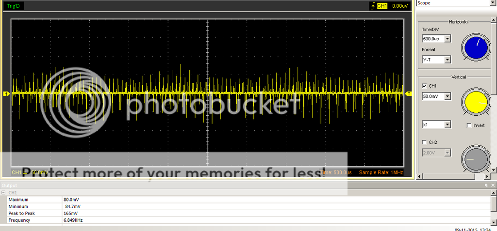
I put the scope across the large resistors that look like a copper jumper, that sit between the banks of FETs and the output filter. I apologize for not knowing what to call them. I was hoping to see a spike in current or something that would indicate why the driver is shutting down. I couldn't find anything on the main board tied to those pins, just a jumper from one side of the board to the other. I've included a screenshot from the scope showing what's going on across the resistors. With the scope on the gates of the output MOSFETs, I don't see any pulses or anything.

I have disconnected everything connected to the SD pins on the 21844s. They are still not coming up to 5V relative to the VSS pins. Does this indicate that I killed (both) 21844s while soldering?
This is becoming extremely frustrating. I feel as if I'm inches away from giving up.
This is becoming extremely frustrating. I feel as if I'm inches away from giving up.
Did you lift the pin from the board?
Many people (including myself) have damaged these ICs when installing them. It's also important that you buy from a reputable distributor. It prevents buying counterfeit ICs. It also ensures that the ICs are properly stored and shipped. Legit distributors will ship in hermetically sealed envelopes with moisture cards and desiccant. Improperly stored/shipped ICs may have to be baked according to the manufacturer to remove any moisture that the IC may have absorbed.
Many people (including myself) have damaged these ICs when installing them. It's also important that you buy from a reputable distributor. It prevents buying counterfeit ICs. It also ensures that the ICs are properly stored and shipped. Legit distributors will ship in hermetically sealed envelopes with moisture cards and desiccant. Improperly stored/shipped ICs may have to be baked according to the manufacturer to remove any moisture that the IC may have absorbed.
I did not lift the leg, but unsoldered the inductor and capacitor that connected them to the rest of the circuit.
The parts were sourced from arrow.com. was in sealed package, and dessicant, notes on the bag about humidity and baking. The ones I installed were immediately after breaking the seal on the bag. Just started replacing them again. taking even more caution this time on heat while installing. I'll probably be posting back in a few minutes after I get all of the legs soldered.
The parts were sourced from arrow.com. was in sealed package, and dessicant, notes on the bag about humidity and baking. The ones I installed were immediately after breaking the seal on the bag. Just started replacing them again. taking even more caution this time on heat while installing. I'll probably be posting back in a few minutes after I get all of the legs soldered.
replaced one of the 21844s. SD is coming up to around 780mV now, was getting to 750 before. Now the LO of the 21844 I replaced is coming to around 180mV on the scope, before it would sit at 0.
Should I replace the other IC and see what happens? everything (as far as I can tell) is disconnected from the SD pins, but they are still tied together.
Should I replace the other IC and see what happens? everything (as far as I can tell) is disconnected from the SD pins, but they are still tied together.
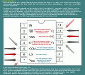
If you have another new IC, check the resistance between the legs of each various section of the IC to see if the ones you installed and removed read precisely the same as the brand new ones.
The image below shows the tests for the driver stages. Also check between the various pins on the control circuit of the IC.
The image below shows the tests for the driver stages. Also check between the various pins on the control circuit of the IC.
Attachments
Mr. Babin sells a tutorial on amplifier repair, you can find details on bcae1.com.
A dear friend of mine bought me the tutorial, and it is an excellent wealth of knowledge. If I would have simply bought the tutorial a couple years ago I would have saved hundreds of dollars in FETs that go up in smoke as soon as power is applied. So many lessons that I learned the hard way.
A dear friend of mine bought me the tutorial, and it is an excellent wealth of knowledge. If I would have simply bought the tutorial a couple years ago I would have saved hundreds of dollars in FETs that go up in smoke as soon as power is applied. So many lessons that I learned the hard way.
- Status
- This old topic is closed. If you want to reopen this topic, contact a moderator using the "Report Post" button.
- Home
- General Interest
- Car Audio
- Powerbass xta4k, DWM3640NHV_V30, IR21844 woes