Hi Perry,
Does the hip4080 drive the outputs? You recommend a IRF3710Z for output fets will the FQP85N06 be okay on the input side? Do you have a favored substitution for it as well. I think this amp was a modded one. I read the other write up and think I had the 1.5KE68A Zener anti feed back protection diodes at the fets but yet it was still installed on HIP4080 chip legs. It also reads that replacing R08 with a 10ohm and R37 with a 75K will increase the rail voltage.It also reads that changing the internal fuse from 20 to 30 amps will allow over-driving the amp at 1/2 an ohm for SPL applications.
Perry the article suggest needing to check the anti feed back diodes at the same time I check the gate resistors. The resistors should be 10 ohms @ 1%.
Can I begin by looking for driver signals at the TC4424?
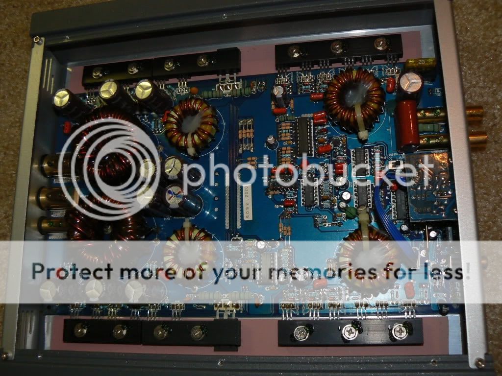
Also this photo taken from the web shows a large ceramic resistor in between the speaker outputs and a bipolar 47Uf cap. Where can I find these items and any idea the wattage rating on the ceramic resistor?
Does the hip4080 drive the outputs? You recommend a IRF3710Z for output fets will the FQP85N06 be okay on the input side? Do you have a favored substitution for it as well. I think this amp was a modded one. I read the other write up and think I had the 1.5KE68A Zener anti feed back protection diodes at the fets but yet it was still installed on HIP4080 chip legs. It also reads that replacing R08 with a 10ohm and R37 with a 75K will increase the rail voltage.It also reads that changing the internal fuse from 20 to 30 amps will allow over-driving the amp at 1/2 an ohm for SPL applications.
Perry the article suggest needing to check the anti feed back diodes at the same time I check the gate resistors. The resistors should be 10 ohms @ 1%.
Can I begin by looking for driver signals at the TC4424?
Also this photo taken from the web shows a large ceramic resistor in between the speaker outputs and a bipolar 47Uf cap. Where can I find these items and any idea the wattage rating on the ceramic resistor?
Last edited:
I will not help modify the amp.
The first color band on the resistor could be either red or brown. It's difficult to see but it's likely a 0.2 ohm. One photo I have shows a 0.47 ohm there. It's likely 2w. Order whatever resistor that matches the dimensions of the one in the amp.
I don't know what an anti-feedback diode is.
The first color band on the resistor could be either red or brown. It's difficult to see but it's likely a 0.2 ohm. One photo I have shows a 0.47 ohm there. It's likely 2w. Order whatever resistor that matches the dimensions of the one in the amp.
I don't know what an anti-feedback diode is.
The resistor is a 0.2 ohm 2 watt..
I have the same amp here on the bench
Thank you Mr Merlington. Do you or anyone else have a source for the 100volt bipolar cap?
Thanks again.
Hugh
Last edited:
I will not help modify the amp.
The first color band on the resistor could be either red or brown. It's difficult to see but it's likely a 0.2 ohm. One photo I have shows a 0.47 ohm there. It's likely 2w. Order whatever resistor that matches the dimensions of the one in the amp.
I don't know what an anti-feedback diode is.
Thank you Perry,
Neither do I know what an "anti feedback diode" is. Thats just what it was designated in the literature I found on the net about the amp. I think it was just the personal nomenclature of the poster. They are for protection of the HIP4080 from all Ive read in several places. I think the amp has already been modded so no biggie. Im just wondering what it all was.
What is your choice for the power supply fets for this amp? Im inclined to run whats original unless the availability or reliability is better running something else.
There were some diode connected (soldered on top of the leads) across the high-side drive on the 4080. They're not needed for your amp because the equivalent diodes are installed near the high-side FETs.
You can use the originals if they're still available from reputable distributors. If not, use the IRF3205. The drive circuit can easily drive them.
You can use the originals if they're still available from reputable distributors. If not, use the IRF3205. The drive circuit can easily drive them.
Hi again,
Pulled this one back out to finish. Not much left I think.
I measured 80 volts dc at the middle legs of D12 and D11 Ps fets look okay may need a second look but the voltage is there and nothing is hot. It's been on idle for awhile now so I looked next at the Vdc on TL4424. This is what I measured. The schematic for the chip shows no connection for pins 1 and 8 but I see measurements.....
pin1 = 53mVdc
Pin2 = 25mVdc
Pin3 = 0 Vdc
Pin4 = 23 mVdc
Pin5 = 22 mVdc
Pin6 = 14 Vdc
Pin7 = 23 mVdc
Pin8 = 100 mVdc
Last edited:
I am also following a guide on this particular amp from decibelcar.com. It suggest all the commonly failed parts and suggest I look at each. Silly and redundant probably but I don't think it will hurt anything. To also gain and idea of what should be seen there on a this working amp for future reference may also be useful.
Would you feel confident at this point to start replacing the output fets? The hip is new so I don't think there is much more in this audio chain to do useful until then.
Suggestions?
Would you feel confident at this point to start replacing the output fets? The hip is new so I don't think there is much more in this audio chain to do useful until then.
Suggestions?
Last edited:
You can't learn much from measuring the voltage. Going from 11v to 14v DC supply voltage and all virtually all readings will change significantly. A scope is much better than a multimeter but still not very useful if you don't understand how the components function. You have to study the datasheets until you understand how the various components work under all conditions.
If the 4080 IC was in the circuit with ANY defective outputs, I would not trust it and would not install the new FETs until you install a new 4080.
If the 4080 IC was in the circuit with ANY defective outputs, I would not trust it and would not install the new FETs until you install a new 4080.
I can understand the data sheets quite well. I had also looked with the scope just hadnt commented on it. The 4080 was replaced. I hope a change in voltage wouldnt change all of them because some of the pins have min and max values so if you probed and something that was out of those ranges it could indicate issues from other areas of a defective chip.
- Status
- This old topic is closed. If you want to reopen this topic, contact a moderator using the "Report Post" button.
- Home
- General Interest
- Car Audio
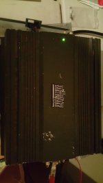
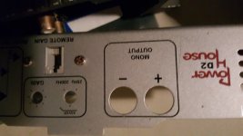
- Earthquake Powerhouse D2