Amp starts and runs drawing 2 amps of current.Its seems to start really hard.Harder than any other amp of its caliber that I've seen.
It has 1.5 dc offset across speaker terminals.
Output transitor ocsillation frequency changes periodically as does current draw.Never losing oscillation though.
I'm assuming made a mistake by probing the 6n137 chips.I touched one pin(can't remember which one) and it went into protect and shorted some outputs.I did NOT hit two pins at once.
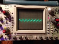
In the included pic is a waveform from the + speaker terminal.Scope was set to 5v/div 10us.Not sure if the triangle waveform in a issue being that it's frequency is so high?
Don't know much about this design.Any advice?
It has 1.5 dc offset across speaker terminals.
Output transitor ocsillation frequency changes periodically as does current draw.Never losing oscillation though.
I'm assuming made a mistake by probing the 6n137 chips.I touched one pin(can't remember which one) and it went into protect and shorted some outputs.I did NOT hit two pins at once.
In the included pic is a waveform from the + speaker terminal.Scope was set to 5v/div 10us.Not sure if the triangle waveform in a issue being that it's frequency is so high?
Don't know much about this design.Any advice?
Attachments
I have a 3000 (double this amp) on the bench right now and it draws enough current to repeatedly shut down a 25 amp power supply until the caps are charged.
The operating frequency seems about right.
The triangle waveform is noise getting through the output filter. The filter cap may be out of tolerance. Shorted inductors are a problem with these amps but yours appears to have an extra insulator.
The operating frequency seems about right.
The triangle waveform is noise getting through the output filter. The filter cap may be out of tolerance. Shorted inductors are a problem with these amps but yours appears to have an extra insulator.
Do you know the inductance of the output coil?
Could that high frequency triangle be the reason for my 1.5vdc dc offset?I checked the few capacitors at the output of the filter inductor and there okay.And I don't believe the inductor is shorted but not positive.
I just have.feeling that the dc offset issue has something to do with the output oscillation frequency changing suddenly and when it changes the current draw on power supply fluctuates momentarily.
Also, do you see a clean square wave on the low side output gates with outputs removed?
I could of swore I had a clean square wave before I installed the outputs.Now I don't have it with outputs removed since some shorted when I apparently made a mistake probing the 137's.
The sinuslive diagram that's generally used for these amps gives 120uH as the value but I measured a couple of inductors that I pulled from massive 1500 boards and they are 85uH.
The low side should be a square wave. Post a screen cap of your drive signal if you're concerned about it.
I've seen the massive amps with up to 3v DC offset with no load. Adding a load to it dropped the offset to well under 1v and didn't increase the current draw any.
The low side should be a square wave. Post a screen cap of your drive signal if you're concerned about it.
I've seen the massive amps with up to 3v DC offset with no load. Adding a load to it dropped the offset to well under 1v and didn't increase the current draw any.
Perry,i was testing the amp with a 1ohm load and 50hz signal.After 5 minutes I noticed the ammeter on the power supply fluctuating rapidly.Noticed that the 50hz signal was not symmetrical and the dc offset went from 300mv to 700mvdc.
After removing input signal the idle current was 1.3.Before test running,it was 2.1.
I've included low and high side drive signals after the amp started being uncontrollable with a load.The pics are with NO input signal.50v/div 2us dc coup.
Also,the output inductor gets pretty hot.Not sure what's acceptable and if perhaps that's the entire issue.if so,I guess I don't understand how the inductor can affect drive signal and the current draw decrease.
Attachments
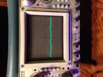
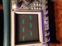
Actually I think the drive signal is okay at the moment.And yes the probe is calibrated.
What's unacceptable for output inductor temp?This one gets to about 210F after running for several minutes.
Also,the rca shield and secondary ground have 900k ohm across them.When rca cable is inserted, the resistance goes too 2Ohm from secondary ground to rca ground shield.And its 0ohms(dead short) from (-)speaker terminal to primary ground.Is this normal?Im not grasping this.
Reason I ask about the rca is because if the amp is on and I try to plug the rca in it starts drawing excessive current and goes into protect.If I remove remote power then insert rca.
And restart it,it seems okay.
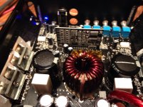
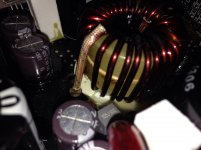
Well,apparently I was focusing too much on looking for shorted windings on the inductor.I obviously overlooked a crack on one of the cores.
If you look close at the bottom inductor you can see a brown spot and a small crack.
I assume that the inductor is toast and I need replace it?
If you look close at the bottom inductor you can see a brown spot and a small crack.
I assume that the inductor is toast and I need replace it?
Attachments
The brown residue may be a coating that tuned brown due to overheating. If it had a short, that would definitely cause it to overheat.
The massive version of these amps used cheap inductor cores which made them run hot.
Inductors and magnet wire can operate at relatively high temperatures with no problem.
I've never intentionally cracked an inductor core to see if it would make a difference but I did it with a transformer core and cracking it did very little. Only after I broke pieces loose and pushed them away from the windings was there a change in the idle current. If the cores overheated, that could have changed the properties of the cores and caused them to run hotter than normal.
- Status
- This old topic is closed. If you want to reopen this topic, contact a moderator using the "Report Post" button.
- Home
- General Interest
- Car Audio
- Audiopipe 1500D issue