Brown, black, silver, gold is 0.1 ohm, 5% tolerance.
Something is wrong with the numbers you posted. Why does it read 2 places to the right of the decimal when touching the probes and 1 place to the right of the decimal when on the resistor?
If all read the same, it's likely that all are OK. There's very little chance that all are out of tolerance and if the defective channel reads the same as the others, they aren't likely the cause of the problem.
Hmmm...must have looked at the 5% by mistake or typed in the wrong starting color on the digi key site. The touching lead number should be 0.00, that "I" is a typo. The at rest number is a 1 at the far left of the meter, i misread the decimal, that shows the meter setting.
So if the thought is the resistors are good, next step?
So if the thought is the resistors are good, next step?
As far as the resistors go, I thought since they all pretty well measured the same, that the 2 emitter resistors were not the issue.
I verified that the transistors were in the right spot as I had taken a picture before removing the transistors, and put them back in the same order, which I think I verified in a previous post.
I haven't tried swapping the transistors from the suspect bad channel to another channel, but that is fairly quick so I guess I can try that as well.
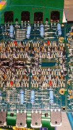
The blue areas on both sides appear to be within spec.
The red circled areas are the location of the bad channel.
I rechecked the output transistors on all four channels, they all meter around the same values on diode mode as listed in a previous post.
The red circled areas are the location of the bad channel.
I rechecked the output transistors on all four channels, they all meter around the same values on diode mode as listed in a previous post.
Attachments
")
So i compared all of the resistors from channel 1 and 2. All of the resistors I have compared match so far. Some are totally different resistors, which doesn't make a whole lot of sense, I would assume that the resistor pairs would match, but I guess not. Example-R109 and R209, one would assume is for channel 1 and channel 2 and that they would be the same resistor.
Again, I'm still learning so any thoughts on that? I don't have a schematic so I'm just going by what seems like are pairs of resistors per channel.
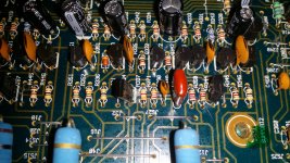
Anyways I was again looking over the board and saw something a might suspect.
Looks like some kind of residue or maybe moisture on the board. Picture attached. The resistor appears to be ok, spec wise, thoughts about the black transistor next to it? I measured it removed from the board in diode mode, using standard B C E, or left to right if reading the text on the transistor:
Negative lead B then positive to middle or C=1 on my meter, no change
Negative lead B then positive to outer leg or E=.559
No other combinations of meter to legs show any readings, 1, no change
Thoughts?
Again, I'm still learning so any thoughts on that? I don't have a schematic so I'm just going by what seems like are pairs of resistors per channel.
Anyways I was again looking over the board and saw something a might suspect.
Looks like some kind of residue or maybe moisture on the board. Picture attached. The resistor appears to be ok, spec wise, thoughts about the black transistor next to it? I measured it removed from the board in diode mode, using standard B C E, or left to right if reading the text on the transistor:
Negative lead B then positive to middle or C=1 on my meter, no change
Negative lead B then positive to outer leg or E=.559
No other combinations of meter to legs show any readings, 1, no change
Thoughts?
Attachments
Why are you checking the resistors? They are generally obviously burned when defective in an amp like this. Did you compare the transistor readings?
The transistor could be defective. You should see ~0.6 from B-C and B-E and open with the leads reversed (out of the circuit).
The transistor could be defective. You should see ~0.6 from B-C and B-E and open with the leads reversed (out of the circuit).
I checked the resistors because i'm an idiot and can't read.
As in, I saw transistor, brain registered resistor, hence the reason I made the previous comment of "I was hoping you wouldn't say check all the resistors".
Clearly reading comprehension was out the window here on my part.
Checking a few transistors is much less time consuming than checking all of the resistors, which I was doing. Oops.
I think the same type of transistor in the board was measuring on both legs as you stated. The one I pulled, only showed any readings on B E.
So to continue testing I need to check the rest of the smaller transistors on the board for that channel for valid readings.
I'll do that and post back the results.
Thanks.
Look what I found...a broken trace. It was mostly obscured by the board leavings but after cleaning with some alcohol and q-tip, it was much more visible.
Not sure what caused this, and my trace repair pen was not much use (older) but I put some silver goo on the trace, checked the trace and it appears to have a solid connection.
Going to let it dry tonight and put some power to it tomorrow to see if that darn blinking stops.
Not sure what caused this, and my trace repair pen was not much use (older) but I put some silver goo on the trace, checked the trace and it appears to have a solid connection.
Going to let it dry tonight and put some power to it tomorrow to see if that darn blinking stops.
Attachments
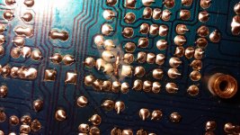
That appears to be a ground trace. It was likely burned when a speaker wire shorted to ground.
In the future, use a piece of wire to jump to each side of the burned area. Remove the loose copper to prevent it from shorting to anything else unless the jumper you use is soldered to the loose copper.
In the future, use a piece of wire to jump to each side of the burned area. Remove the loose copper to prevent it from shorting to anything else unless the jumper you use is soldered to the loose copper.
- Status
- This old topic is closed. If you want to reopen this topic, contact a moderator using the "Report Post" button.
- Home
- General Interest
- Car Audio
- Crossfire tek504 Repair