Well, I got a weird issue with this one that I have not seen before.
The Sub/Class-D section is not running, and the Power/Protect LED is not lit at all.. It flickers very quickly when applying remote but thats it.
However, all 4 main channels are working fine with sound though.
So, not really sure where to look next. This amplifier is discrete in the class-D section, no driver IC and no indication on where the 15V regulator is for powering that section.
Anyone have a schematic, or thoughts?
An externally hosted image should be here but it was not working when we last tested it.
Yes, I have rail voltage. Both of them. There are 2 sets. the high voltages for the class D section, and lower voltages for the +/-15V regulators, and the Class AB section.
Oscillation I did not check, but the outputs are cold to the touch with only 1.3VDC on the gates, and -1.3VDC on the compliment side. The output inductor is intact. Including the solder joints. Also, the pre-amp sub output from the pre-amp board is ok.
Oscillation I did not check, but the outputs are cold to the touch with only 1.3VDC on the gates, and -1.3VDC on the compliment side. The output inductor is intact. Including the solder joints. Also, the pre-amp sub output from the pre-amp board is ok.
Gonna dig this thread back up again. This amp was shelved when I left the job and moved on. Well now its back in my possession as I never fixed it. Also pacparts isnt showing anything for this model except some type of cable.
So I need the schematics. How do I get Kenwood schematics?
So I need the schematics. How do I get Kenwood schematics?
Nevermind, I found it.
PacParts: 823E20-7686-77
Going to attempt to order it. Not holding my breath though.
PacParts: 823E20-7686-77
Going to attempt to order it. Not holding my breath though.
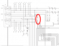
Studying the schematic, and based on my symptoms of no power LED, and no Class D section, BUT with the SMPS actually still running producing voltage, leads me to the TL494 Pin 3. FEEDBACK. It appears it is being used as an OUTPUT to drive a pair of logic transistors Q861, and Q862. Since one of the error amplifiers is locked out, the 2nd one is used to turn on and off the power supply.
Power supply is running. But that means pin 3 is still producing a voltage which is why the D section is locked out, and no LED.
But here comes the kicker: All datasheets and diagrams specify pin 3 as an input. Why in blue blazes would Kenwood engineers violate this rule and treat the pin as an output? that is asking for disaster. Almost as if they did that on purpose.
Thoughts?
Pin 3 can be an input or an output. I don't see the distinction or in/output on the datasheets. The pin is tied, internally, to the input of a comparator with a CCS of 0.7ma to ground. The two error amps are "or'd" to the same comparator.
Post the voltage on all terminals of the 494.
Post the voltage on all terminals of the 494.
Checked that back when I was working on this thing and it was ok.
I remember reading in the datasheet of the TL494 that the electrical specifications shows it as an input? and that it has an internal bias sinking current of something another I will have to go back and look.
I remember reading in the datasheet of the TL494 that the electrical specifications shows it as an input? and that it has an internal bias sinking current of something another I will have to go back and look.
Ok this is getting crazier by the minute.
Turns out TL494 isnt the issue so that is my mistake there.
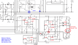
However after tracing this circuit for an hour or so, it appears to be in TMUTE lockout.
There is an 8.66V difference between the internal ground, and the external power ground. If I force those 2 grounds together with an external jumper wire, the Power LED comes back on because that voltage difference goes away, however the D section is still in mute. These 2 grounds are actually tied together internally with a couple of resistors. If I measure the resistance between PGND and SGND I get the resistance of those 2 added together so I know this is NOT the problem.
So I decided to remove that jumper and take some voltage measurements which I have posted below.
Any thoughts?
Turns out TL494 isnt the issue so that is my mistake there.
However after tracing this circuit for an hour or so, it appears to be in TMUTE lockout.
There is an 8.66V difference between the internal ground, and the external power ground. If I force those 2 grounds together with an external jumper wire, the Power LED comes back on because that voltage difference goes away, however the D section is still in mute. These 2 grounds are actually tied together internally with a couple of resistors. If I measure the resistance between PGND and SGND I get the resistance of those 2 added together so I know this is NOT the problem.
So I decided to remove that jumper and take some voltage measurements which I have posted below.
Any thoughts?
Attachments
I'd suggest shorting primary and secondary grounds and follow signal through the amp. It's possible that an op-amp (may be able to find by cooling/defrosting) is shorted internally.
I've also seen protection circuits do this where a transistor on the secondary was driven on and was driving something in the protection circuit (on the primary side of the supply). This shifted the entire secondary up.
I've also seen protection circuits do this where a transistor on the secondary was driven on and was driving something in the protection circuit (on the primary side of the supply). This shifted the entire secondary up.
if I put an Ammeter between the two grounds I get about 5mA of current.
Also I have all my audio signals including the sub signal out of the pre-amp board.
I will double check the Class AB section of the Amp, but I think it was producing audio. it was only the D section that was dead, all voltages are there including the B+ for the drivers, and the 5V for the logic section.
Last edited:
Found it. I realized that the Class D amplifier was turned off through the muting, but the DC-DC converter was not.
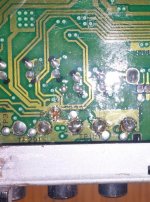
So I traced it all back, and found that Q671 had a 0 ohm short across its gate and source. That of course dumped the 13V or so into the secondary ground bus, lifting up the bus.
Then, since the transistor was shorted internally, the Drain was not, So it wasnt pulling to ground disabling Q672, so it was staying muted.
Soon as I removed Q671, the ground difference stabilized. Then I jumped Drain to Source as expected in operation, and everything came alive and the amplifier started singing to me. All 5 channels.
So thats it. That little bugger there. Now out of every semiconductor that could possibly short and unexpectedly short under load like the outputs, etc. This little transistor in the enable/mute circuit shorts. Things like this scratch my head.
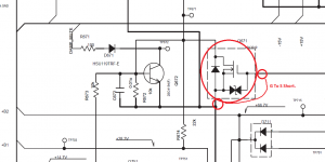
Attached is the schematic with the affected transistor.
So I traced it all back, and found that Q671 had a 0 ohm short across its gate and source. That of course dumped the 13V or so into the secondary ground bus, lifting up the bus.
Then, since the transistor was shorted internally, the Drain was not, So it wasnt pulling to ground disabling Q672, so it was staying muted.
Soon as I removed Q671, the ground difference stabilized. Then I jumped Drain to Source as expected in operation, and everything came alive and the amplifier started singing to me. All 5 channels.
So thats it. That little bugger there. Now out of every semiconductor that could possibly short and unexpectedly short under load like the outputs, etc. This little transistor in the enable/mute circuit shorts. Things like this scratch my head.
Attached is the schematic with the affected transistor.
Attachments
- Status
- This old topic is closed. If you want to reopen this topic, contact a moderator using the "Report Post" button.
- Home
- General Interest
- Car Audio
- Kenwood KAC-7005PS weird issue