Hello,
managed to get my hands on an another alpine mrv 1000 (I still curse the day I sold the first one )
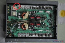
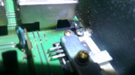
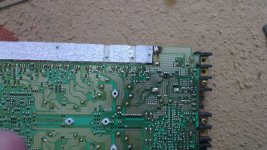
I haven`t gotten the time to run it, but I noticed that on the inside of it there is a big burnt area next to the power suply.
better yet ...between the power suply and the ground screw.
I edited a picture for you, beucase I am runing late on a visit I have to have, but I hope you get the general idea, before I come back home and start puting on the real pictures.
as I told you, I haven`t gotten the time to run it yet. the dude that sold it to me, told me it works. if not he told me to ship it back to him.
what could go wrong? What could not start at the power up?
cheers !
managed to get my hands on an another alpine mrv 1000 (I still curse the day I sold the first one )
I haven`t gotten the time to run it, but I noticed that on the inside of it there is a big burnt area next to the power suply.
better yet ...between the power suply and the ground screw.
I edited a picture for you, beucase I am runing late on a visit I have to have, but I hope you get the general idea, before I come back home and start puting on the real pictures.
as I told you, I haven`t gotten the time to run it yet. the dude that sold it to me, told me it works. if not he told me to ship it back to him.
what could go wrong? What could not start at the power up?
cheers !
Attachments
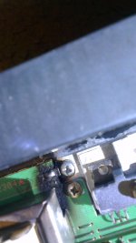
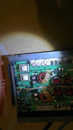
so here are the pictures of the amp
as I can see, as far as that little "damaged" area, the rest is ok. no burnt areas.
what should I be checking with my multimeter when I hook it up?
what are the proper steps in following to see if the amp works out fine?
as I can see, as far as that little "damaged" area, the rest is ok. no burnt areas.
what should I be checking with my multimeter when I hook it up?
what are the proper steps in following to see if the amp works out fine?
Attachments
Looks almost like your amp was hooked up to 12 volts backwards < reverse polarity on the power connections > There will be more damage if this is the situation.
I suggest that You should remove all the golden colored screws holding the aluminum plates to the inside of the amp and look at the bottom of the board. You won't have to take the transistor screws out just the gold looking ones in the aluminum plates under the power devices. Once you do this you can lift the board out and disconnect the LED connector and pull that thru the board so the board is free from the sink. Then a bottom view is possible, and there is probably more damage below the board where your not able to see now.. Just suggesting....a bit more investigation before trying to power it up any more.....
I suggest that You should remove all the golden colored screws holding the aluminum plates to the inside of the amp and look at the bottom of the board. You won't have to take the transistor screws out just the gold looking ones in the aluminum plates under the power devices. Once you do this you can lift the board out and disconnect the LED connector and pull that thru the board so the board is free from the sink. Then a bottom view is possible, and there is probably more damage below the board where your not able to see now.. Just suggesting....a bit more investigation before trying to power it up any more.....
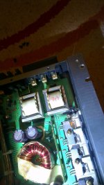
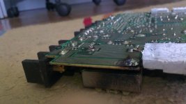
so it looks like the damage is a bit wors then expected. but still as far as I can see, limited here.
I will check the diode, that prevents shorscircuits to see what it says.
any tips on later?
I will check it in and out of the circuit board.
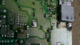
the rest of the circuit board looks clean
p.s.
how can I fix the exfoliated circuit board? any solutions on that?
taping a big steal plate to it? leading on to the ground screw, I believe it will do no harm
I will check the diode, that prevents shorscircuits to see what it says.
any tips on later?
I will check it in and out of the circuit board.
the rest of the circuit board looks clean
p.s.
how can I fix the exfoliated circuit board? any solutions on that?
taping a big steal plate to it? leading on to the ground screw, I believe it will do no harm
Attachments
Last edited:
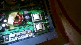
just talked to the previous owner.
he told me, that the burnt mark over there, was done because he had a not so thick. and because the cable was so thin on the -, that happened.
he told me that it works no problem.
should I plug it in?
p.s.
measured the diode, put the multimeter in automode, and showed me 154.9 on the diode.
I own a lutron - cm 9930 multimeter
The amp was trying to ground through the heatsink which was likely screwed down to the vehicle body when the ground wire was too small.
should I hook it up and test it ?
Sure. If the 3rd leg of the PS FETs on that side read 0 ohms to the ground terminal, there isn't likely to be any significant damage.
pls be more specific. ps fet is wich one of them?
am I to understand that I will hold one probe to the ground and one to the 3-rd feet no?
Are you checking this diode in the circuit or out of the circuit?
If this is the reverse protection diode, it's not shorted so it may be OK.
When checking diodes, for the most definitive readings, the diode needs to be checked out of the circuit. Generally, it's only possible to tell if the diode is shorted in the circuit.
If this is the reverse protection diode, it's not shorted so it may be OK.
When checking diodes, for the most definitive readings, the diode needs to be checked out of the circuit. Generally, it's only possible to tell if the diode is shorted in the circuit.
got the diode out of the circuit board,
I`m getting in auto mode 153.9 n F...don`t know what they are :-s..
In other facts, I tested for continuous sever components. The "ohm" function goes through, an they ring up as "connected". (like the mass with the power trans, mass with the burnt area and so on). SO I guess that its a good thing.
one thing I have to ask before I hook it up to test it, If I clean the exfoliated area on the back of the board that I`ve show you in the pictures, and try soldering it back, can I get that area to stay "on the board" ?
Or should I live it like that? Can some exces in power cause any problmes in the future because the aera is not stuck on properly?
On diode check, you should read open in one direction and about 0.6v with the probes reversed on the diode.
how does the multimeter show "open status on diode mode" ??
- Status
- This old topic is closed. If you want to reopen this topic, contact a moderator using the "Report Post" button.
- Home
- General Interest
- Car Audio
- Problem with an Alpine MRV1000 amp