Pins 5 and 7 of the IR4427S connect to the bases of the 2 BCP53/56 pairs. So, I take it I have to connect pins 9 and 10 of the lanzars TL494 to where the pins 5 and 7 are for the IR4427??
Then, you mentioned something about a mod to prevent over shooting the rail voltage. So, I'll just wait till I hear back from you on that part. Tomorrows another day. Thank you as always.")
Then, you mentioned something about a mod to prevent over shooting the rail voltage. So, I'll just wait till I hear back from you on that part. Tomorrows another day. Thank you as always.
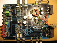
This will be an easy one to work with.
Before we go any farther, you should know that I've never tried this with any of the Brazilian amps. I don't expect any problems but there's always a risk.
Remove the 4427 and clean the pads.
Both amps will have to be connected to the 12v power supply. Make absolutely sure that you cannot possibly lose ground to the Lanzar during the testing.
You'll need to remove all components connected to pin 4 of the 494.
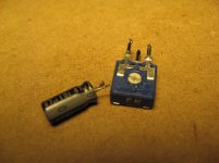
You'll need a potentiometer. Virtually any value will work but something between 1k and 10k will probably work the best.
The low side of the pot will connect to 494-7 (pin7). The high side of hte pot will connect to 494-14. The wiper of the pot will connect to 494-4. Also connect a capacitor of 10-100uf between pins 4 and 7 of the 494.
Power up the lanzar and confirm that you can control the output pulse width smoothly.
Before we go any farther, you should know that I've never tried this with any of the Brazilian amps. I don't expect any problems but there's always a risk.
Remove the 4427 and clean the pads.
Both amps will have to be connected to the 12v power supply. Make absolutely sure that you cannot possibly lose ground to the Lanzar during the testing.
You'll need to remove all components connected to pin 4 of the 494.
You'll need a potentiometer. Virtually any value will work but something between 1k and 10k will probably work the best.
The low side of the pot will connect to 494-7 (pin7). The high side of hte pot will connect to 494-14. The wiper of the pot will connect to 494-4. Also connect a capacitor of 10-100uf between pins 4 and 7 of the 494.
Power up the lanzar and confirm that you can control the output pulse width smoothly.
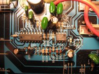
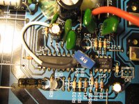
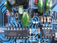
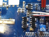
I removed 2 resistors and a cap that were on pin 4. The cap that was between pins 14 and 4 (100uf 25v) I relocated to where one of the resistors were (between pins 4 and 7) placing the neg side on a trace for pin 7 (gnd). The pot I attached to where the other resistor was (between 4 and 14). The low side I connected to ground (essentially pin 7) , the high side to pin 14 and the wiper to pin 4.
I also ran a double wire that is connected to pins 9 and 10 (to run to other amp).
I also ran a double wire that is connected to pins 9 and 10 (to run to other amp).
Attachments
Last edited:
Sorry Perry... darn holidays.
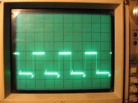
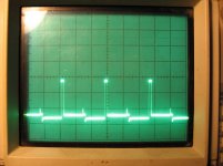
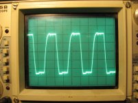
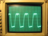
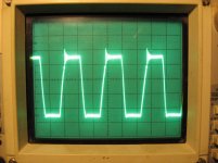
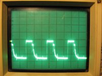
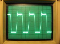
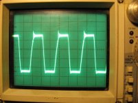
Yes it does... all the way counter clockwise yields almost a 50% cycle. The second pic shows how short I can make the cycle before it breaks up turning clockwise. It does move from one to the other smoothly. It uses about half of the pots range.
Do I connect the wire from pins 9 and 10 of the 494 to the BCP Pair bases? and just power up both? (Having both directly connected to the same power source)
Yes it does... all the way counter clockwise yields almost a 50% cycle. The second pic shows how short I can make the cycle before it breaks up turning clockwise. It does move from one to the other smoothly. It uses about half of the pots range.Do I connect the wire from pins 9 and 10 of the 494 to the BCP Pair bases? and just power up both? (Having both directly connected to the same power source)
Attachments
Last edited:
It should be that simple. Start with the pulse width at the minimum. Have either a small fuse or a current limiter in line for the large amp.
Increase the pulse width slowly so that you don't exceed the rail voltage.
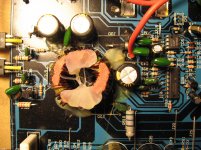
If there is excessive current draw, confirm that you have a good drive signal reaching the FETs in the large amp. If you have a good drive signal and the current draw is excessive, it could be due to a shorted transformer. Twist all transformers to see if that makes a difference.
If it powers up and the various supply voltages are developed, see if you can find any faults that could be preventing the amp from powering up.
Increase the pulse width slowly so that you don't exceed the rail voltage.
If there is excessive current draw, confirm that you have a good drive signal reaching the FETs in the large amp. If you have a good drive signal and the current draw is excessive, it could be due to a shorted transformer. Twist all transformers to see if that makes a difference.
If it powers up and the various supply voltages are developed, see if you can find any faults that could be preventing the amp from powering up.
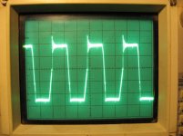
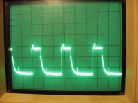
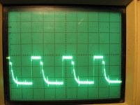
I can power it up without excessive current draw without the remote wire attached to the large amp. I get a decent looking square wave, until I add remote for the big amp. At that point, it pulls current and the wave drops. I attached 2 pics. There is currently no outputs in the amp, they all tested fine as did the drivers. The yellow clip light blinks 16x as it did before
Attachments
Last edited:
The pot says 256v on one side and 397v on the other side.
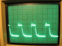
The drive wave form does change a little bit. These pics are after I adjusted the pot on the small amp till I got to around 240volts. Caps are only rated for 250v and yet they say to go past that?
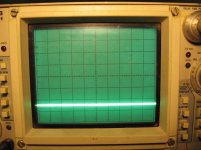
Anyway, the first 2 pics are from the drain tabs on the ps transistor. The spiked one is without remote, it then drops a bit with remote applied. The other 2 are from pin 9 of the 494. The wave does seem to change a little bit when remote is applied.
The drive wave form does change a little bit. These pics are after I adjusted the pot on the small amp till I got to around 240volts. Caps are only rated for 250v and yet they say to go past that?
Anyway, the first 2 pics are from the drain tabs on the ps transistor. The spiked one is without remote, it then drops a bit with remote applied. The other 2 are from pin 9 of the 494. The wave does seem to change a little bit when remote is applied.
Attachments
- Status
- This old topic is closed. If you want to reopen this topic, contact a moderator using the "Report Post" button.
- Home
- General Interest
- Car Audio
- SounDigital SD16KD-SMD