Power supply and gate resistors were burnt, pulled supply fets and removed gate resistors. Powered up the amp and checked the drive signal, looked good and measured 4.75v with the meter. Outputs and diode checked out OK. Replaced 47ohm gate resistors, and power fets. Checked continuity between drivers through the 47 ohm resistors to the power fet, all looked good. Powered up the amp and it played fine for about 15 minutes at 60% output then it tripped my supply. Now amp will not power up and appears to be a dead short between the positive and negative terminal. Power fets, outputs and diode check ok. Anyone have suggestions on what to check next? I'm going to pull the power fets and see if the amp will power up.
I pulled the outputs, amp turns on fine and produces rail voltage. The outputs check OK but the first review of the drive signal indicates I might have an issue on the high side fets. I've not jumped the opamp pins yet or put the jumpers on the low side to take measurements. So far I've set the scope to AC coupling and looked at the waveform on the gate pads.
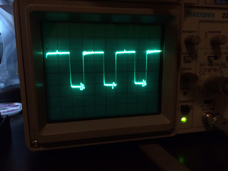
Scope settings: 5volts/div, 5us, AC coupling
From left to right looking from the front of the amp towards the heat sink (Q504-507) the signals looked as follows:
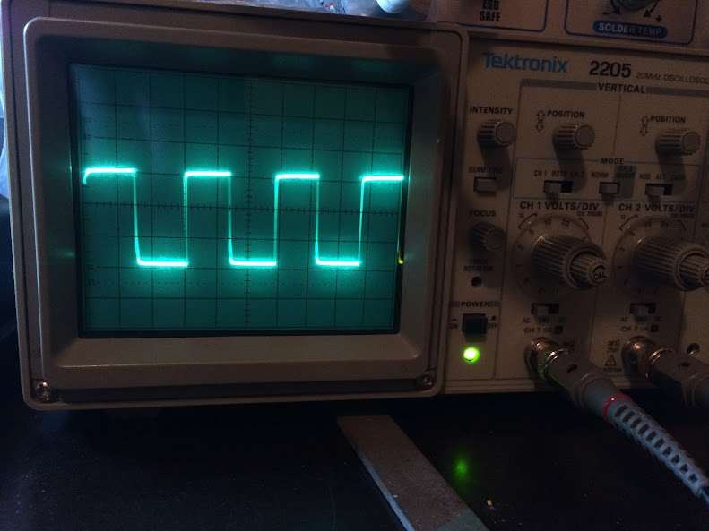

It looks like the high side has something funky going on. I'll jump pins 1and 2 on the opamp to see if it changes anything.
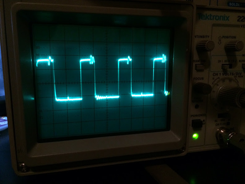
Scope settings: 5volts/div, 5us, AC coupling
From left to right looking from the front of the amp towards the heat sink (Q504-507) the signals looked as follows:
It looks like the high side has something funky going on. I'll jump pins 1and 2 on the opamp to see if it changes anything.
Last edited:
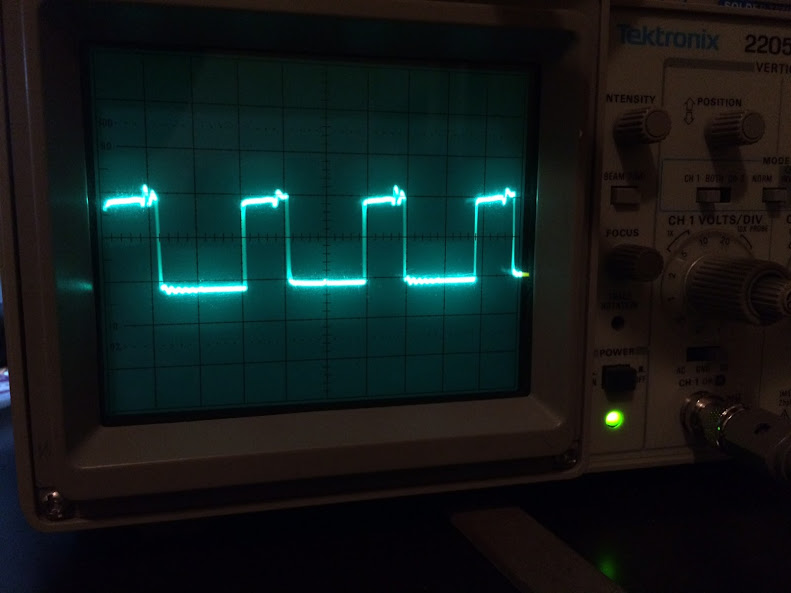
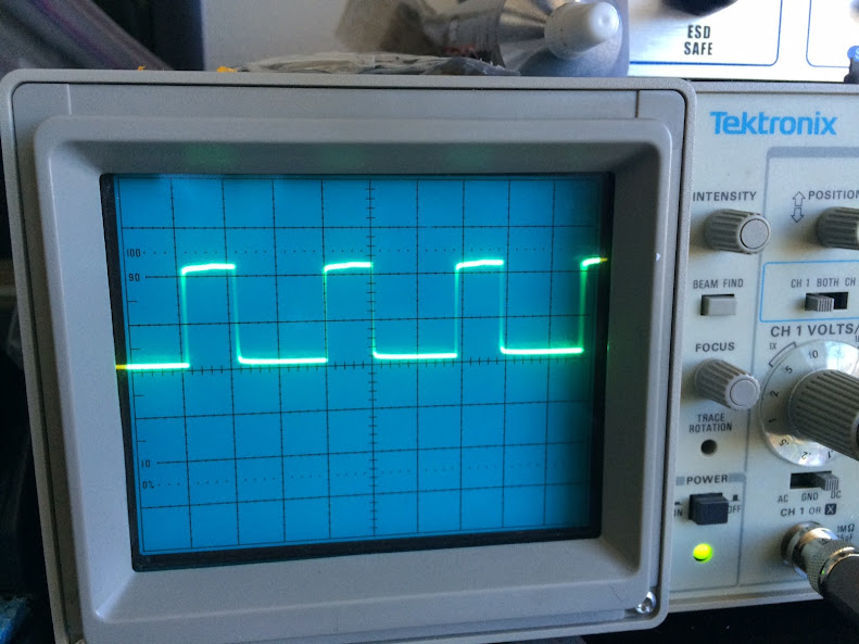
Ok, with opamp pins 1 and 2 jumped I get the following:
Duty Cycle - Volts
Q504: 35.5% 4.08v
Q505: 61.5% 9.08v
Q506: 35.5% 5.27v
Q507: 61.3% 7.07v
I'm not entirely sure what I'm looking for in the wave forms but they appear to have a lot of ringing. Images are in order from Q504-507
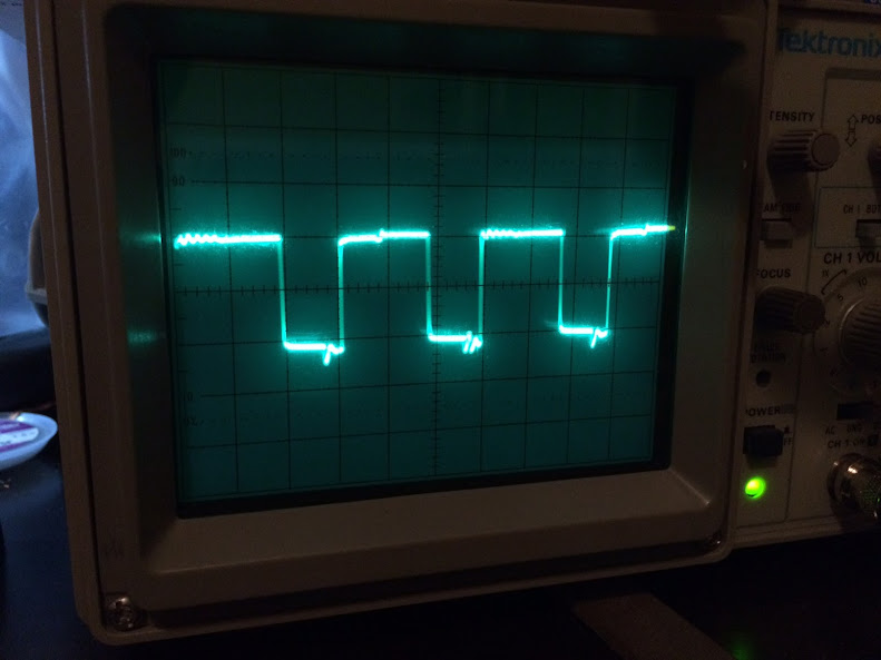
Is it common for q500 and q511 to run hot enough to not want to touch them?
Duty Cycle - Volts
Q504: 35.5% 4.08v
Q505: 61.5% 9.08v
Q506: 35.5% 5.27v
Q507: 61.3% 7.07v
I'm not entirely sure what I'm looking for in the wave forms but they appear to have a lot of ringing. Images are in order from Q504-507
Is it common for q500 and q511 to run hot enough to not want to touch them?
Last edited:
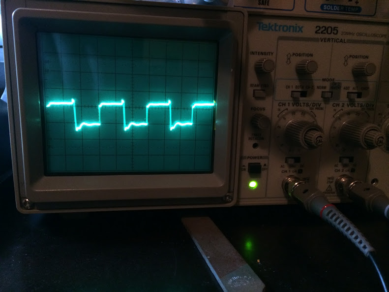
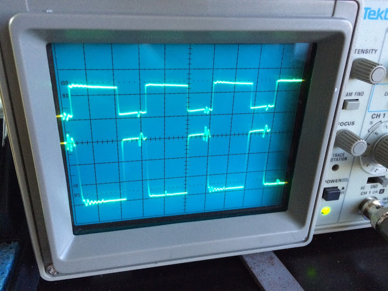
The second set are dc coupled with the jumpers installed on the low side fets. The traces are in sync with each other ( when the high side is on the low side is off and vise verse) I can shift the traces to all start with a leading edge at the 0,0 point is that what you mean by no reference line?
The high side fets appear to never reach the 0 line when they are switched off. the traces stays about a line width above 0 until right before it switches back on.
Q504 is the bottom trace, Q505 is the top trace, I moved the trace for Q505 up so they were not over lapping. to aid in comparing them with each other.
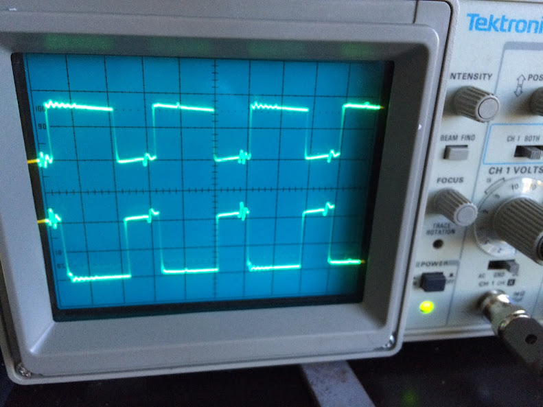
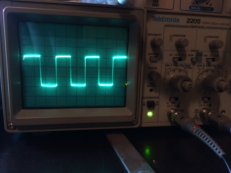
Q506 is the bottom trace, Q507 is the top trace, I moved the trace for Q507 up so they were not over lapping.
Q504 is the bottom trace, Q505 is the top trace, I moved the trace for Q505 up so they were not over lapping. to aid in comparing them with each other.
Q506 is the bottom trace, Q507 is the top trace, I moved the trace for Q507 up so they were not over lapping.
The tests on the semiconductor testing page of the tutorial and the test on the following page catch virtually all defective FETs.
Basic Amplifier Repair - Transistor Test Applet Link
Are the transistors you used as replacements from the same batch as the ones that were in the amp?
Basic Amplifier Repair - Transistor Test Applet Link
Are the transistors you used as replacements from the same batch as the ones that were in the amp?
The originals test OK, I'm starting to lean more towards a potential capacitor issue. If I have bad rail caps or main power supply caps could that cause the amp to have an abnormally high current draw (enough to blow a 10 amp fuse on power up). Once the amp is on and as long as I do not disconnect the battery connection it will cycle on and off without issue using the remote wire. Idle current when operating is 1.75 amps. Standby current is .07 amps
Last edited:
- Status
- This old topic is closed. If you want to reopen this topic, contact a moderator using the "Report Post" button.
- Home
- General Interest
- Car Audio
- JL Audio 500/1Ver. 10