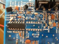
Sorry for the mistake, I had about 2 VDC on pin 8, 9, 10 of IC2. Pin 8 is connected to R130A. R130A is connected to R131A (that goes to IC1) and also with a resistor near hi- level input (I think it takes signal from hi level input).
Now without IC2 I have no DC voltage on op amps inputs/outputs. Only on IC1's pin 1 I have about -11 VDC (but this pin is unused).
Now without IC2 I have no DC voltage on op amps inputs/outputs. Only on IC1's pin 1 I have about -11 VDC (but this pin is unused).
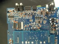
Attachments
Op-amps are relatively difficult to destroy. They can generally have their outputs shorted to ground or either supply and still survive. Are you sure that the op-amps are really being damaged?
It's unlikely that there is a problem with the supply voltage feeding the op-amp that would cause only this op-amp to fail.
It's unlikely that there is a problem with the supply voltage feeding the op-amp that would cause only this op-amp to fail.
The first ones that i removed had DC voltage on input/output pin when I only connected +Vcc and -Vcc (with op amp out of the board and with external supply).
Now what can I do? Reinstall IC1 and IC2 and try to find where is the problem?
PS: IC2 became so hot, maybe I have to check better if there are other pins with DC that can cause over heating...?
Now what can I do? Reinstall IC1 and IC2 and try to find where is the problem?
PS: IC2 became so hot, maybe I have to check better if there are other pins with DC that can cause over heating...?
Last edited:
Check for DC with the op-amp removed.
Install it in a socket to allow you to remove it easily for tests that may be required.
Was the op-amp new or pulled from another board?
Was the op-amp from a reputable distributor?
It's possible that you installed a defective op-amp (semiconductors are generally tested but it is possible to get a DOA IC). Even with the output shorted, the op-amp won't get very hot due to internal current limiters. The only time that I'd expect to see an op-amp over heat would be with an over-voltage condition, with it installed backwards or if it's shorted internally.
Op amps are new from TME. I remember that at the first power up with new op amps I saw square wave on lm293, but after a bit of seconds there where nothing. Maybe my pc soundcard doesn't work good (I had problems in the paste). Can pc sound card have produced DC voltage and damage tl074 internally?
The sound card couldn't harm the IC. The amp is likely AC coupled at the input. Even if DC coupled, the 2.5v of output from a soundcard won't do any harm.
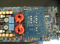
You may want to confirm that there is no short from primary to secondary. With the black probe on the main ground and the red probe on the negative speaker terminal (meter set to DC volts), twist/push/pull on the transformers to see if the DCV ever changes from 0v to something near 12v.
You may want to confirm that there is no short from primary to secondary. With the black probe on the main ground and the red probe on the negative speaker terminal (meter set to DC volts), twist/push/pull on the transformers to see if the DCV ever changes from 0v to something near 12v.
I think there isn't short from primary to secondary. There is something like square wave (see attachment) with the black probe on the main ground and the red probe on the negative speaker terminal. If I push transformer there is a very little change on amplitude of the waveform, but limited to millivolts.
I reinstalled IC1 and IC2, replaced all TL072 on control board. Now there is no DC on op amp input/output pins. With 50hz sine wave there isn't square wave on output mosfet's gate pad. What can I do?
I reinstalled IC1 and IC2, replaced all TL072 on control board. Now there is no DC on op amp input/output pins. With 50hz sine wave there isn't square wave on output mosfet's gate pad. What can I do?
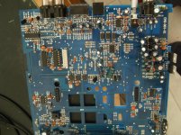
Attachments
I'm assuming that the pin configuration for all 3640 boards is the same. If so, pin 3 on the center connector is the audio input.
Audio will not be visible there if the output stage is working properly (will have rail-rail oscillation on the output transistors). When the output stage is working, the output cancels the audio there so audio has to be checked on previous op-amp output pin or one of the components between that op-amp and the input pin of the driver board.
Audio will not be visible there if the output stage is working properly (will have rail-rail oscillation on the output transistors). When the output stage is working, the output cancels the audio there so audio has to be checked on previous op-amp output pin or one of the components between that op-amp and the input pin of the driver board.
- Status
- This old topic is closed. If you want to reopen this topic, contact a moderator using the "Report Post" button.
- Home
- General Interest
- Car Audio
- Hertz HP1D problems