I was wondering if anyone had taken the time to try and rewind any output filter choke on the JL Audio amps. If so how successful was the rewind? Is it possible to find something off-the-shelf that is close enough to match the original? Most class D amps I've ever seen use a toroid style not a E style on the output.
A bit of both actually, I picked up an amp pretty cheap that I can salvage driver boards and other components if fixing them is to difficult or expensive to be economical. If fixing or replacing them turns easy and relatively cheap I would probably keep this one for myself .
To clarify, it's an inductor, not a transformer.
Try PM'ing wrenchone. His profile states that he's a switching PS engineer. He would be able to definitively tell you what would be needed.
Information from the amp.
* Frequency of oscillation: 58kHz (seems low but the amp appears to be in good working order)
* Maximum voltage: 82v
* Current: 500 watts into 4 and 1.5 ohms
* Measured inductance of original inductor: 60uH (2 measured, 59uH for one, 61uH for the other)
* Wire used: 2 strands of 18g
You have to consider core material as well. For example. molypermalloy cores run cooler but cost more than others (which generally tend to run hotter). You have to decide what's most important. There are always tradeoffs.
Last edited:
The shape of the core isn't important as long as the replacement fits but I don't know that finding one that handles the current and has the right inductance makes it a good replacement. That's why I suggested that you PM that user. A magnetics engineer could fill in a lot of blanks.
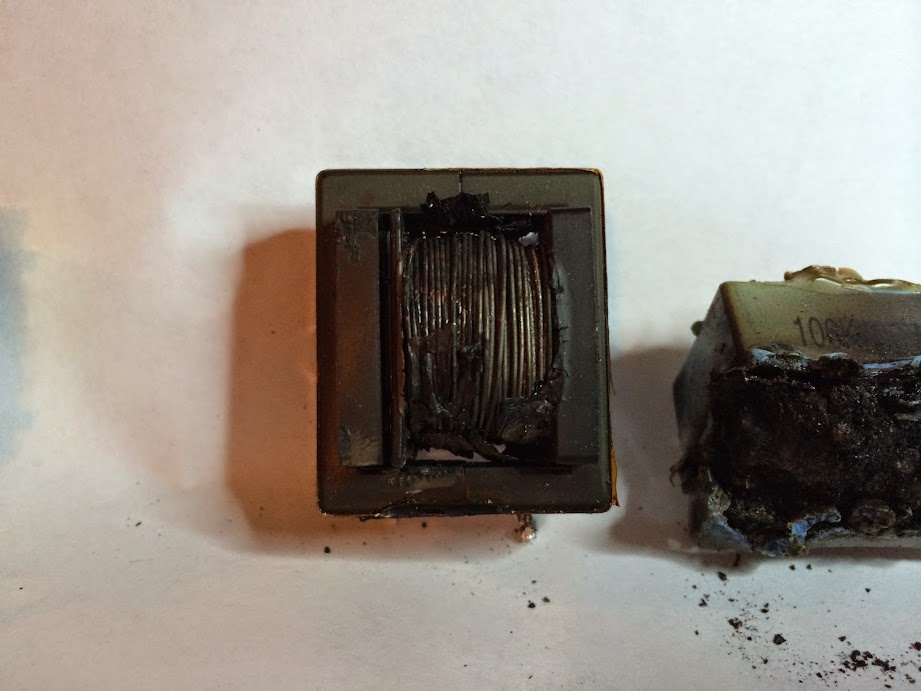
I would say its safe to say this inductor is pretty useless. I'm not sure I entirely understand what would cause that and the capacitor on the outputs of a 500/5 to get so hot. The capacitor made a huge mess of things and is going to take a while to get everything all cleaned up. Is it possible that the core of the inductor is still OK and can be salvaged?
If its salvageable it doesn't look like it would be too bad of a task to rewind with the 6 strands of wire and have it look almost normal. But then again I've never attempted to wind something on a bobbin like this.

If its salvageable it doesn't look like it would be too bad of a task to rewind with the 6 strands of wire and have it look almost normal. But then again I've never attempted to wind something on a bobbin like this.
Last edited:

The subwoofer section of the 500/5 is basically just like the smaller 250/1 isn't it? I figured the power supply or outputs of this amp would be shot considering the damage to the inductors and capacitors on the output. Somehow they seem to check out OK. I've noticed the driver boards in the 300/2, 300/4 and now the 500/5 all seem to look pretty much identical. Are they interchangeable with one another?
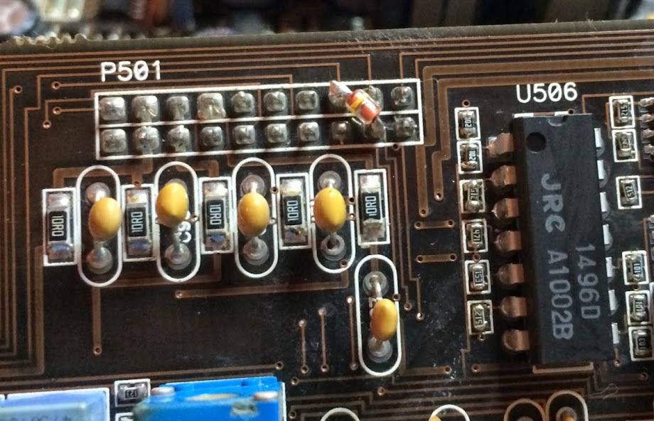
Looks like the diodes were a major after thought.
Looks like the diodes were a major after thought.
Last edited:
I figured if this amp was too far gone that I might use one of its driver boards in my 300/4 that has one that seems to have a short in it somewhere that i've been unable to locate. Removed all the resistors off the board checked them and have basically mapped out the whole board point to point and still haven't found the cause. I've pretty much thrown in the towel on tracking down its problem.
Ok, I've cleaned up as much of the mess as possible, found some minor damage on the pre-amp board by the exploded output capacitor. Looks like it was literally on fire or pretty near. Have three traces that are detached from the overheated portion of the board. (all still have good conductivity through them though so I'll worry about them later. With the burned parts removed I powered up the amp to check some voltages.
*low ohm light comes on first, goes out and the power light comes on, then after 2-3 seconds the low ohm light will flash and go out. Power light stays on, the aux supply appears to be working and producing +- 43 and the +-15 on the 4 channel side of the amp.
*I have 61 volts at the subwoofer supply, +- 26ish on the rear channel supply, and +40 -26 on the front channel supply. (all dc volt measurements were made on the backside of the power supply inductors)
4 channel power supply fets have a gate voltage of 4.2 volts, and the sub side reads 1.4 volts
In your opinion should I start with the 4 channel side of the amp which doesn't seem to be too out of whack except for the possible low rail voltage on the front channel, or dive right into the sub channel that has some clear issues?
by "backside" I was referring to the leg of the inductor furthest away form the rectifier diode connection. Looks like one side is attached to the rectifier and the other leg appears to be attached a capacitor. At the negative diode center leg it shows -26.81, the inductor shows -26.81 volts on one leg and -26.78 on the other. I've not checked the amp to see if it produces sound at this point but I did check for dc offsets at the speaker terminals and they are all around .00x volts on the 4 channel side.
- Status
- This old topic is closed. If you want to reopen this topic, contact a moderator using the "Report Post" button.
- Home
- General Interest
- Car Audio
- JL Audio Output Inductor