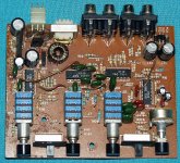
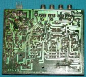
I have a power question for this active XO. I am wanting to use it along with this project from ESP (a subwoofer phase controller). I am wanting to use this in a home environment and powered by a linear PSU that plugs in the wall (US voltage). The +/-15vdc for the phase controller isn't a problem but, I would rather, if possible, not have to also build a separate +13.6vdc supply just for the XO. Below are pics of the PCB, both the component side and the trace side. I have flipped the trace side pic over so that it matches the component side.
I know just about zero about switch mode supplies which I'm sure the EX-3 uses to get the proper voltage for the JRC7001 opamps. But, I do recognize a bridge rectifier when I see one. I noticed the 4 diodes in the upper right corner and followed them for a bit. What I found was 2 caps (C53 & C54) that tied into each voltage rail and on to ground. from there the traces went to pins 4 and 11 of the JRC7001. These pins, I believe are Vdd and Vss respectively.
Upon measuring the voltage at C53 & C54, I found +14.18vdc and -14.22vdc, when measured against ground. Normally, at this point, I would look up the datasheet for a JRC7001 and confirm everything but, that isn't so easy. The only datasheet I can find is for a NJU7001/7002/7004. I am assuming (and would like confirmation) that the NJU7004 is the same as an old JRC7001. If my assumption is correct, then I have this figured out. Just lift the rectifier diodes from the PCB and tie in the +/-15vdc their. If they are different, in regards to power requirements, does someone know what the JRC7001 needs? Both appear to be 14 pin quad opamps.
This is a nice old school active XO and really don't care to fry it. The safe way would be to build 2 PSUs but, if I can get away with one, all the better.
Looking forward to (more like hoping) Perry Babin responding. You have helped me once with a old HiFonics Pluto and I really respect your knowledge.
THANKS!
Attachments
It has come to my attention that the quad opamp that I called a "JRC7001" is in fact a "074D". This explains a good bit as part of my concern was that the datasheet for the NJU7004 called for a single supply where as the datasheet for a 074D calls for a dual supply. This addresses a good bit of my concerns.
Although I appreciate your confidence in me answering your questions, asking for help from any member by name may discourage others from answering your questions.
The only other thing that you may want to check is the resistance between the primary and secondary (shield) grounds. It's likely that they have a 1k ohm resistor between them. If so, you'll need to use the secondary ground as the connection point for the AC mains supply that you intend to use.
The only other thing that you may want to check is the resistance between the primary and secondary (shield) grounds. It's likely that they have a 1k ohm resistor between them. If so, you'll need to use the secondary ground as the connection point for the AC mains supply that you intend to use.
Thanks, Perry. I didn't mean to put anyone else off but, it's like when you find a good car mechanic, you tend to go back to them. That's not to say that no one else can do the job just as well.
I checked for continuity between where C53 & C54 ground (secondary ground?) and the ground where it normally comes in to power it in a car environment (primary ground?) and found no continuity between the two. My original intent was/is to ground on the secondary side anyway and totally cut off the switch mode section on the PCB by lifting the rectifier diodes and grounding to the trace used for C53 and C54 grounding.
I checked for continuity between where C53 & C54 ground (secondary ground?) and the ground where it normally comes in to power it in a car environment (primary ground?) and found no continuity between the two. My original intent was/is to ground on the secondary side anyway and totally cut off the switch mode section on the PCB by lifting the rectifier diodes and grounding to the trace used for C53 and C54 grounding.
- Status
- This old topic is closed. If you want to reopen this topic, contact a moderator using the "Report Post" button.