i made a box with fans for my amps. I use a relay that hook up to themastat. when fans turn on or off it pops in speakers.Back when i had a care with pionts i put a cap in and it stop speeker niose would that work here. Where would i put it on the remote wire or that goes to the ciol in the relay or the power wire that goes to the fans
Diode
Did you place a back EMF diode across the relay coil ?
Just a simple 1n4004 or something similar will do .
Cheers ,
Rens
i made a box with fans for my amps. I use a relay that hook up to themastat. when fans turn on or off it pops in speakers.Back when i had a care with pionts i put a cap in and it stop speeker niose would that work here. Where would i put it on the remote wire or that goes to the ciol in the relay or the power wire that goes to the fans
Did you place a back EMF diode across the relay coil ?
Just a simple 1n4004 or something similar will do .
Cheers ,
Rens
i will try but can you explain how this would stop the popping?Ive been trying to learn as much as i can on builds and repairs. ive done alot of builds and have got good at chasings nioses in car stereo witch in most cases has been bad grounds.This is the 1st build that ive used fans and thank you
Have a read of this and hopefully it will explain:
Tutorial on back EMF suppresion: its causes and its cures.
Tutorial on back EMF suppresion: its causes and its cures.
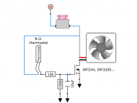
If you're willing to add a few components (resistor, capacitor, FET) to the circuit, you could turn the fans on gradually. This may eliminate the pop.
As a side note, I don't think a turn-on pop could be caused by back EMF. If the back EMF solutions, don't work, try the FET.
As a side note, I don't think a turn-on pop could be caused by back EMF. If the back EMF solutions, don't work, try the FET.
Attachments
If you're willing to add a few components (resistor, capacitor, FET) to the circuit, you could turn the fans on gradually. This may eliminate the pop.
As a side note, I don't think a turn-on pop could be caused by back EMF. If the back EMF solutions, don't work, try the FET.
Nice
")
I agree about the turn-on pop , but it's worth a try. The thermostat could have some contact bouncing when switching on .
Cheers ,
Rens
Last edited:
Hi,
What king of fan do you use?
220V (110V) AC or you use 12V DC fans like computer style?
In case of 12Vdc/24Vdc from were you take power?
Hi sesebe ,
This is the CAR audio part of DIYaudio ,
I think you know the answer now .
Cheers ,
Rens
fans
12v dc i have 2 0g wire run to back of car one goes to battiery in trunk the other feeds the smaller amps and the power lead for fans the relay goes to remote of deck
Hi,
What king of fan do you use?
220V (110V) AC or you use 12V DC fans like computer style?
In case of 12Vdc/24Vdc from were you take power?
12v dc i have 2 0g wire run to back of car one goes to battiery in trunk the other feeds the smaller amps and the power lead for fans the relay goes to remote of deck
irf510
got all except the only mosfet i got is IRF510 will that work
If you're willing to add a few components (resistor, capacitor, FET) to the circuit, you could turn the fans on gradually. This may eliminate the pop.
As a side note, I don't think a turn-on pop could be caused by back EMF. If the back EMF solutions, don't work, try the FET.
got all except the only mosfet i got is IRF510 will that work
board
this works great i have all the parts to make another one. Is there a board or way of making this so i can use it in the car and not have mess that i had. I did put a heat sink on it but after 10 min it was warm but the sink stayed cool. thank you for all your help.
If you're willing to add a few components (resistor, capacitor, FET) to the circuit, you could turn the fans on gradually. This may eliminate the pop.
As a side note, I don't think a turn-on pop could be caused by back EMF. If the back EMF solutions, don't work, try the FET.
this works great i have all the parts to make another one. Is there a board or way of making this so i can use it in the car and not have mess that i had. I did put a heat sink on it but after 10 min it was warm but the sink stayed cool. thank you for all your help.
Pops can be radiated or conducted or both.
Radiated is by electromagnetic waves.
Conducted is by wires.
I would first try a reverse biased diode across the relay coil.
You could even try a small capacitor across the relay contacts.
I used to run a mobile disco that used record decks.
The decks motors were switched mains and they would cause massive pops in the speakers when switched on and off.
I put 100nf 250VAC capacitors across the switches and that worked a treat.
Sorry, I have not seen that is CAR AUDIO forum.
The relay MUST have a reversed diode across the coil as close as posible to relay pins (you can solder directly on coil relay pins). Across the coil you can put a small capacitor 0.1u with short pins and serie with the coil (inserted on wire that come from thermostat) a 2.2-10ohm/0.25-0.5W. This will filter the noise.
If you decide to use the circuit from post 5, it is ok. If the transistor get hot it is not normal.
How much power need the fan ?
The thermostat output it is ON/OFF ?
The MOS transistor must work ON/OFF with a small ramp-up - ramp-down during the comutation.
Anyhow with the tranzistor on heatsink, the tranzistor must have almost the same temperature with the radiator. If not, you have a bad heat trasfer and you need silicone grease.
On the schematic change the resistor report: serie 2K2 and paralel 470K (G-S).
Changing the value of the resistors won't make the transistor run cooler. The values given will drive about 11v to the FET (Vgs). Increasing the voltage above that won't make any appreciable difference in the Vds-on. Better thermal mating or an FET with lower Rds-on (like those listed on the diagram) will help to decrease the operating temperature of the transistor (if it's a problem).
- Status
- This old topic is closed. If you want to reopen this topic, contact a moderator using the "Report Post" button.
- Home
- General Interest
- Car Audio
- fans relay pop