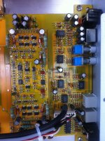
Alright so this is the amp I have been working on recently and after getting it back together I noticed the RCA output's were missing. After replacing the outputs and further investigation I noticed the audio section near the RCA outputs had some missing caps and some where moved around a bit. I am not sure if those are originally 4.7uf 50V?
I have a hifonics 2006D with the section near the rca's is nearly identical and it uses a combination of 1 uf and 47 uf capacitors.
What im trying to find is the capacitor values or for C101 - C108 and
CF1-CF2 located right behind the rca outputs outlined in red in the first photo.
I have a hifonics 2006D with the section near the rca's is nearly identical and it uses a combination of 1 uf and 47 uf capacitors.
What im trying to find is the capacitor values or for C101 - C108 and
CF1-CF2 located right behind the rca outputs outlined in red in the first photo.
An externally hosted image should be here but it was not working when we last tested it.
An externally hosted image should be here but it was not working when we last tested it.
Last edited:
Yeah when I received the amp the capacitors were like that and the amp still worked fine after I did some work replacing the driver transistors and mosfets but there was no rca output jack like you see in the photo. So after it was all working properly I decided to add the rca output jacks and didn't realize the capacitors were not where there sapose to be. I tried testing the output jacks and assuming I shorted something because now the amp is pulling excessive current when I connect the remote lead.
I think I've seen that picture or one similar in the forums but I can't read the cap values. I need more of a side view or even better you could read me the capacitor values when you get to the lab from the ones I have circled in your photo here:
An externally hosted image should be here but it was not working when we last tested it.
Last edited:
Sorry for a late reply.
In the board i have there have been some factory mods.
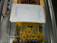
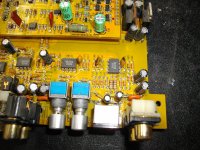
Although C101 and C103 are both 4.7uF/50V (see photo),
there is another 4.7uF with positive leg connected to the positive pad of C108 and its negative leg connected to the minus pad of C105.
And another 4.7uF with its positive leg to C107 positive pad and its negative leg to the minus pad of C106.
Hope this helps.
In the board i have there have been some factory mods.
Although C101 and C103 are both 4.7uF/50V (see photo),
there is another 4.7uF with positive leg connected to the positive pad of C108 and its negative leg connected to the minus pad of C105.
And another 4.7uF with its positive leg to C107 positive pad and its negative leg to the minus pad of C106.
Hope this helps.
Attachments
There was no rca output jack when I received this and I ended up replacing it. After doing so I just noticed the caps where in different places and I didn't think it would be a factory mod. I wasn't getting any rca output after replacing the jacks and something shorted out when I plugged the outputs in.
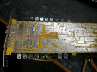
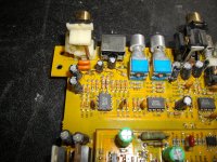
I may be at fault but I was hoping I could trouble you for one last photo of the underside of the board near the outputs.
Mine had capacitors on the bottom with the legs broke and I have no clue where they were at in the first place. Also I had some red jumper wire on the bottom also. I just happen to be so lucky is to have you with the same amp.
you are very lucky as i have photos of the amp i repaired last year, and i have an identical one (unfinished) at the lab right now.
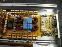
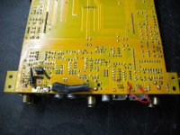
If you feed the amp with a low frequency signal, and the preamp is ok, you should see the signal in these two pins of the second pic (one is input to the module and the other is GND for signal).
If you feed the amp with a low frequency signal, and the preamp is ok, you should see the signal in these two pins of the second pic (one is input to the module and the other is GND for signal).
Attachments
") Gives you a good reason to test that new camera out!
Gives you a good reason to test that new camera out!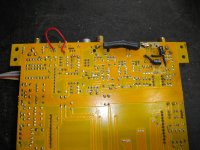
- Status
- This old topic is closed. If you want to reopen this topic, contact a moderator using the "Report Post" button.
- Home
- General Interest
- Car Audio
- Hifonics Colossus XX Capacitor Help