Voltages appear to look correct..
Before putting new outputs in the amp check the following..
Check all the inductors/chokes..
They have a green body and the color bands are yellow purple black,, set your meter to diode check and test them they sould read 0.03 on diode check do you get any reading differnt then 0.03 ??
Also you must replace The Driver IC (IR21844S) that goes to the bank were u had a shorted output..
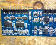
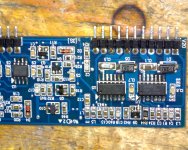
Also post a high res pic of the Audio driverboard again so I can see it and make sure you have all transistors and resistors in the right locations..
Before putting new outputs in the amp check the following..
Check all the inductors/chokes..
They have a green body and the color bands are yellow purple black,, set your meter to diode check and test them they sould read 0.03 on diode check do you get any reading differnt then 0.03 ??
Also you must replace The Driver IC (IR21844S) that goes to the bank were u had a shorted output..
Also post a high res pic of the Audio driverboard again so I can see it and make sure you have all transistors and resistors in the right locations..
Digital Cameras, Sony Cyber-shot DSC-W170 Digital Camera Test Image
It seems to be fairly good. That's a macro sample. View it full size to see how much detail it captured.
It seems to be fairly good. That's a macro sample. View it full size to see how much detail it captured.
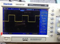
After replacing all 4 driver ICs and checking all components one by one
I re solder the driver board back to the amp.
Using the scope I'm getting signal on 8 of the 16 transistors gates, the first 4 and the last 4 of every shoulder Have no signal, also the duty cycle looks like 40% ON 50% OFF.
Please see picture.
I re solder the driver board back to the amp.
Using the scope I'm getting signal on 8 of the 16 transistors gates, the first 4 and the last 4 of every shoulder Have no signal, also the duty cycle looks like 40% ON 50% OFF.
Please see picture.
Attachments
- Status
- This old topic is closed. If you want to reopen this topic, contact a moderator using the "Report Post" button.
- Home
- General Interest
- Car Audio
- Digital design