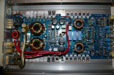
Alright, cleaning out my garage and decided I'd like to try to get a few of my amps out of the boneyard and back up and running again. I'd like to start with this hifonics because it appears to be in the worst condition and I'm hoping I can learn enough from this one to not need as much help on the next. I've read through most of the stuff on BCAE several times and been through most of the hifonics threads on here and other threads with amps that used similar parts. Some of it was quite helpful, but most seemed to fizzle out as soon as you started digging past the testing of transistors.
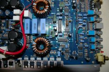
I'm not sure what happened to this thing, but whatever it was appears to have taken out the entire rail on both sides. Most of the fqp65n06's were blown apart, the rest are shorted. All of the irf3710's leak between the drain and source. All 4 rectifiers test bad. The only thing I'm not sure about is the single tip41c, but I'm not real sure what that is or if I'm testing it properly.
Thanks to this site, I have been able to source all of the bad parts I've found so far. I see that the irf3710's should be replaced with irf3710z's and that I should replace the hip4080 if the 3710's were bad. I haven't placed an order yet or tried to replace anything because it's a lot of parts to replace and I want to make sure nothing else is wrong with the board before I put all the new stuff in and watch it smoke.
All I have done so far is remove the 65n06's from the board. Nothing else appears to be visually burned or damaged. I've tested most of the resistors and they seem to have the same resistance as like colored resistors on the board. Just not real sure where to go from here. Any help is greatly appreciated. I do not have a scope, just an autoranging extech dmm, and a 55a power supply.
Last edited:
Been playing with it a little more and I think I've found a few resistors that are not within tolerance.
R202c, R203c, R201c, and r200c all appear to be the same color, and matching pairs on opposite sides of the board.
R202c and R203c both read 42 ohms, R201c reads 128k ohms, and R200c reads .42m ohms. I'm having a hard time reading the colors off of these, but appears to be yellow, violet, yellow, gold, so I'm assuming the R200c is the only one even remotely close to being in tolerance?
R35c, R34c, R32c, and R33c also appear to be the same colors and in matching pairs on opposite sides of the board. R35c and R34c read 42 ohms. R32c and R33c both read 100 ohms. If I'm reading the colors correctly, these should all be 100 ohm resistors.
Sorry if I am not testing these properly. I will definetely need some guidance...
Last edited:
If one output transistor has failed, you should replace all of them. It's likely that the 4080 has failed as well.
The diode ZD1C commonly fails. It's a 6.2v Zener.
Some of the power supply drivers may have failed. Order the BD140 as a sub.
Check the large resistors and diodes near the 4080.
The diode ZD1C commonly fails. It's a 6.2v Zener.
Some of the power supply drivers may have failed. Order the BD140 as a sub.
Check the large resistors and diodes near the 4080.
Those resistors test good.
Do the diodes need to be pulled from the board to be tested properly? I'm having a hard time getting a reading that makes sense to me from any of the diodes on this board or any of the boards I have around for that matter. I have googled and youtubed this, but still struggling. I am not getting the readings I'm looking for. For instance, on the zd1, meter set to diode check, I get .563 reversed and .582 reversed. I am thinking I should see OL when reversed, is that not correct?
Guessing I need to get the new transistors installed before I can test the drivers?
For this Zener, the problem is drift in breakdown voltage. It typically drifts up from 6.2v (±10%). If it gets too high, the output stage won't function.
The diodes on the gates of the output transistors are in parallel with the gate resistors. They rarely fail (I've never seen one fail). The rectifier diodes will appear shorted between the outer legs due to the connection to the secondary windings on the transformers. They should not read shorted from the center leg to the outer legs.
You need to be specific. Which transistors? I'm assuming that you're referring to the power supply FETs and their drivers. You can power up the amp (no FETs installed) and measure the DC voltage on the gate solder pads for the FETs. They should all read the same and should be no more than about 0.7v less than the voltage on pin 9 of the power supply driver IC.
Sorry the transistors I was talking about were the power supply and output fets. The fqp's and irf's on the rail. I am assuming the fqp's are the power supply side and the irf's are the outputs? I am picking this up as I go. I greatly appreciate your patience with me.
I'm having to google all this, but I'm assuming the power supply IC is IC2 on the board, a ia494ap? If that is correct, I'm getting 5.3 on pin 9 and 4.91 at all the gate pads, so we are within tolerance there.
The diodes on the gate, I haven't quite figured out how to read yet anyway, so I guess it's a good thing they rarely fail. The rectifier diodes, if we are talking about the one's that look similar to a transistor (d19c, d19c1, d20c, d20c1) read shorted in every way I place the meter. Outer legs to outer legs and outer legs to center leg.
For the zener (zd1), I'm just not sure yet how to test that. I think I need power on the board in order to figure that out, but with all of the power supply fets removed I won't be able to do that. I did attempt to get a reading there when checking the gate pads, but I just get a reading of .2 on both sides, not enough for it to work and give me a reading. If it is likely to fail, I will just go ahead and order a replacement and swap it out while I'm in there.
The term 'rail' is generally used when referring to supply voltages. They are clamped to the heatsink, not the rail.
Please re-read the basic amp repair page on the bcae1.com site.
To check a diode that's connected in parallel with a resistor, you have to desolder at least one leg of the diode.
It's virtually impossible to have two failed rectifier diodes (D19, etc).
Yes, you have to apply power to check the voltage across ZD1C.
After removing the rectifier diodes from the board, they test properly.</p>
I read the page again and obviously did not read it as thouroughly as I convinced myself I had. I will read through a few more times over the weekend and probably go ahead and purchase the full tutorial. Thank you for your help thus far. Hopefully my next volley of questions will not be so amateur.")
I read the page again and obviously did not read it as thouroughly as I convinced myself I had. I will read through a few more times over the weekend and probably go ahead and purchase the full tutorial. Thank you for your help thus far. Hopefully my next volley of questions will not be so amateur.
- Status
- This old topic is closed. If you want to reopen this topic, contact a moderator using the "Report Post" button.
- Home
- General Interest
- Car Audio
- Hifonics BX1605D