I have no problem with that, I dont need that many but want to get them because I am sure we will be repairing these amps for years to come and soon they just wont be available anymore.
There are subs but I like retaining the factory part and look after a repair ya know?
Yeah man, I agree 100%
")
Still having problems.....
I have discovered that the bias is not stable.
I adjusted the bias to the point where dc offset was at its lowest point that I could get it to be ( -.055v ) and the amp would idle at ~2 amps. I have found that as the amp warms up, I would have to constantly readjust the bias to keep the current draw at ~2A. The increase of current was very slow (~0.5A every 4-5 min.) After 15 minutes of just letting the amp idle and hoping the amp would essentially settle, a current spike occurred and ultimately shorted a couple of the output fets. I must have gone through 2 dozen fets at this point trying to figure out what's going on with these two channels :-(
Any thoughts?
Yes, of course.Still having problems.....
I have discovered that the bias is not stable.
I adjusted the bias to the point where dc offset was at its lowest point that I could get it to be ( -.055v ) and the amp would idle at ~2 amps. I have found that as the amp warms up, I would have to constantly readjust the bias to keep the current draw at ~2A. The increase of current was very slow (~0.5A every 4-5 min.) After 15 minutes of just letting the amp idle and hoping the amp would essentially settle, a current spike occurred and ultimately shorted a couple of the output fets. I must have gone through 2 dozen fets at this point trying to figure out what's going on with these two channels :-(
Any thoughts?
You are mixing 2 *very* different things ... and of course you have trouble.
BIAS and OFFSET are completely different adjustments, an unrelated (or "related" only by chance)-
If to get 55mV offset you bias your amp to 2 Amperes, you are COOKING it.
No wonder it starts heating uncontrolled, current rises a lot (0.5A per 5 minutes) and you have to constantly keep readjusting the Bias pot.
That's called Thermal Runaway .
No wonder your Fets die.
Adjust bias to the value suggested by the Factory (which should be less than 100mA) and adjust offset with "the other" trimmer .... if any .... and if not, leave it as is.
There is no bias compensation circuit in these amps. Set the bias so that the amp is stable (no noise/oscillation. If you touch the probe to the output pin of the op-amp that's driving the channel, you will see that it's very noisy when under biased. Increase the bias very slowly to the point where the output pin of the op-amp gets to be a straight line. There should be a point where the output of the op-amp is quiet and the current draw through the channel is minimal. Try it there to see if it holds.
There is no bias compensation circuit in these amps. Set the bias so that the amp is stable (no noise/oscillation. If you touch the probe to the output pin of the op-amp that's driving the channel, you will see that it's very noisy when under biased. Increase the bias very slowly to the point where the output pin of the op-amp gets to be a straight line. There should be a point where the output of the op-amp is quiet and the current draw through the channel is minimal. Try it there to see if it holds.
Thanks Perry,
I'll give this a shot. Correct me if I'm wrong, but it sounds like the dc offset is to be ignored then? I'm just trying to understand this correctly since I've always been under the impression that offset should be accounted for and minimized as much as possible
Also, my concern is that the two other "untouched and working" channels do not act like these two channels that I have been working on. For example, dc offset for the two good channels remains at a respectable .005v and is "not" effected by adjusting the bias pot.
Ok, I have accomplished the procedure that you had mentioned above.
I adjusted the bias for all four channels to the point where the output pins on the op-amps were clean/flat. This also took care of the dc offset (~.008v per channel now)
I let the amp idle and continuously checked the inline current meter. Initially, the amp drew ~1.5A. After approximately 15 minutes, I noticed that current draw had increased to ~2A and the op-amp's output pins for these two (bad) channels was distorted again. I readjusted the bias, and the current dropped back down to ~1.5A. So I let the amp idle even more, but this time I was not going to readjust the bias. After another 15 minutes or so, the current crept back up to 2A and the op-amps outputs were distorted once again. I let the amp continue to idle (over 2 hours now) and the amp is stable while still drawing 2A of current (output pins still distorted though), but it doesn't appear that the current is going to creep up any higher.
The other two channels are working fine and holding their bias/ offset settings.
Thanks!
You now need to test it with a load (all transistors clamped, fan not necessary because you need it to heat up). Let it heat up about 10° and see how the idle current has changed.
What do you mean by 'distorted' when referring to the output of the op-amps?
Sorry, what I mean is the op-amps output pins are "noisy"
With the loads connected, I'm assuming that this is still just testing at idle... no signal going into the amp?
You now need to test it with a load (all transistors clamped, fan not necessary because you need it to heat up). Let it heat up about 10° and see how the idle current has changed.
Done! I just drove the amp (both "repaired" channels 4 ohm load each) with a sinewave for a good 20 minutes and let the amp warm up significantly.
The amp drew ~1.5A at idle when first fired up (cool to the touch) and after the 20 min run, current draw only icreased by ~0.25A. So even when warmed up idle current was still less than 2A. After the run, the output pins for each op-amp remained clean/flat and there was no more dc offset present.
This is all great, but I'm just wondering why the amp is acting differently than my previous testing. I haven't done anything different to it other than present a load.
Thanks
Just scored another 25 D41D8 transistors from a gentleman in Canada at a very good price.
Nice score!!!
DC can do wierd things in these old amps. Sometimes these amp are stable and sometimes they are haunted....lol!!!
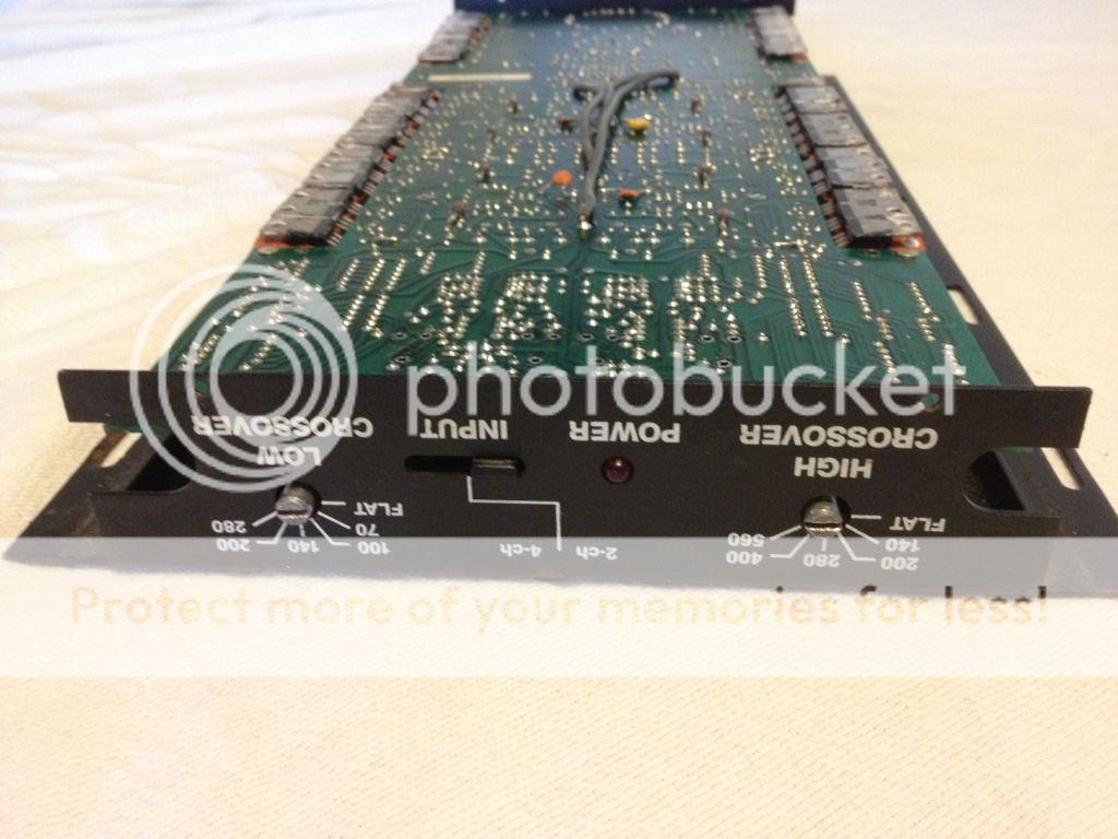
I have 2 brand new bottom covers for these amps and I noticed you had a green board version which was the last models before they were discontinued. My 4 power 650's were all the older models with the DIN which I removed and replaced with RCA jacks of course.
The selector switch for 4 channel and 2 channel must be different on the later models, like a very small switch. The hole in the sheet metal I have is very small and cannot accomedate the older version slide switch.
I was wondering if you could post a pic of the switch on your board and the bottom cover where the switch comes through???
DC can do wierd things in these old amps. Sometimes these amp are stable and sometimes they are haunted....lol!!!
I have 2 brand new bottom covers for these amps and I noticed you had a green board version which was the last models before they were discontinued. My 4 power 650's were all the older models with the DIN which I removed and replaced with RCA jacks of course.
The selector switch for 4 channel and 2 channel must be different on the later models, like a very small switch. The hole in the sheet metal I have is very small and cannot accomedate the older version slide switch.
I was wondering if you could post a pic of the switch on your board and the bottom cover where the switch comes through???
Sure man. I'll snap a couple pics in the morning for you.
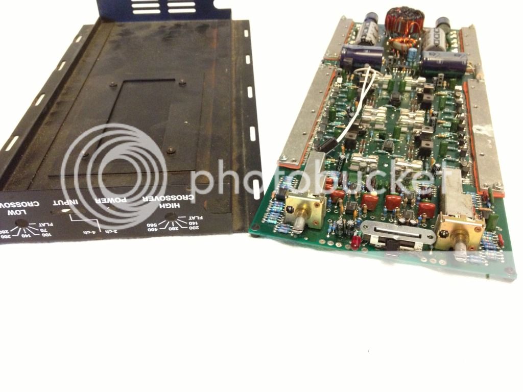
I have two of these 650's here. One "newer" one has the green board and the shroud has the larger 4" fan.
I also have an older one which is the one giving me a hard time
No thats perfect, the bottom covers I have are still different. Maybe they were a defect?
Where the 2 channel/4 channel switch is it is a very small opening. Maybe like they were going to give the 650 a facelift an modernize it a little then came up with the DSM's and bagged it.
These are brand new bottom covers. I could modify them to work, be nice to find a switch that would work with the slot that is cut ya know?
Sean, give us a few pics of these bottoms.
yeah.... please do. Inquiring minds want to know
- Status
- This old topic is closed. If you want to reopen this topic, contact a moderator using the "Report Post" button.
- Home
- General Interest
- Car Audio
- Rockford Fosgate Power 650