I have this amp disassembled it was smoking a little. When I opened it, I found a shorted Fet. I did a bit of research but was unclear.
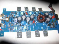
Om each channel their are 4 Transistors. From left to right, they are
SMW20P10, SMW45N10, Orion 0490-0210, Orion 0490-0210.
It is my understanding that the NPN-PNP are the Amplifier and the others are are for the regulator. I have read a few other sites that contradicted this. I also read that the ICs tied to the toroid are the power ICs. The 4 on the right would be power?
How do I determine a replacement? The Orion 0490-0210 are obsolete and there is no cross reference for them.
Attachments
IRFP044 will probably work, you can also likely use the IRFP054 or 64 series < higher rated current >. I suspect the gate drivers fried when the fet died, and while your at it, you might ohm out all the audio outputs looking for a shorted fet in the audio side. I have rarely seen a power supply die and it not be cause cased by a blown channels outputs being shorted, or a bad rectifier diode in the supply. < cause and effect, symptom blown power supply and its root cause a blown channel or shorted diode in the supply >
By the way the SWM chips are the audio stages outputs and the Orion 0490-0210 numbered device are the power supply mosfets. I am guessing the rectifier diodes are on the bottom of the board somewhere as i don't see them in you photo and Orion was known for mounting power supply diodes on the bottom of the board.
Due to the age of the amp your working on its highly unlikely that you will find exact replacement parts. the good news is that today's modern parts are much better engineered and are more durable. You might have to alter the gate resistors when changing out mosfets to get the drive right for the different fet characteristics. Back when this amp was made mosfets were no where near as robust as they are today. So finding better grade parts should be easy, making them work correctly in the circuit design will task your abilities more so then finding usable replacement parts.
I would only replace any damaged outputs and I would replace them as a N and P pair. Also check the little gate driver transistor to any damaged outputs as they tend to get scorched when a output fails.
On the power supply i would replace all four of the mosfets so both of the primary windings see the same device types, Also here again check the little transistor connected to the gate leads they tend to go bye-bye also when fets short out.
What is the resistors value connected to the gate leads of the power supply fets? you might have to run a lower value like 33 or 47 ohms to make the driver circuitry operate properly. <<< Maybe you might need to do this >>>
This amp is not that powerful so the IRFP044 devices should be realistic for current handling this amp requires. If you were to use IRFP064N devices I would only install one pair, one device on each side of the PC Board. As I said modern mosfets are more robust then those used to build this amp back in the 90's, so less parts is actually more power nowadays..
Hope some of this helps...")
On the power supply i would replace all four of the mosfets so both of the primary windings see the same device types, Also here again check the little transistor connected to the gate leads they tend to go bye-bye also when fets short out.
What is the resistors value connected to the gate leads of the power supply fets? you might have to run a lower value like 33 or 47 ohms to make the driver circuitry operate properly. <<< Maybe you might need to do this >>>
This amp is not that powerful so the IRFP044 devices should be realistic for current handling this amp requires. If you were to use IRFP064N devices I would only install one pair, one device on each side of the PC Board. As I said modern mosfets are more robust then those used to build this amp back in the 90's, so less parts is actually more power nowadays..
Hope some of this helps...
Thanks for the Tips. Some of it was too complicated for me so I took a chance. I swapped in the IRFP044 and the outputs. It works! I think it is getting hotter than my other working Cobalt 260. BTW. In your opinion, would 2 cobalt 260s be more transparent and dynamic than a Kaption HO 50.4. I am running the amp from Phoenix gold crossover. Amp (s) are needed to drive 2 dynaudio tweeters and 2 dynaudio woofwers in my studio.
Thanks
Thanks
I swapped in the IRFP044 and the outputs. It works! I think it is getting hotter than my other working Cobalt 260.
Measure your DC offset across the speaker terminals < No signal, amp turned on and no speakers connected > The Dc voltage should be in the milli-volts DC range hopefully less then 30 mvdc. Chances are the drivers are leaking which could be causing the amp to run hotter then normal. As I recall there is no bias adjustment so its preset if present at all. Chances are something is still amiss for the amp to be running hotter then the other.
As for your other question I have no experience with the later mentioned amp so my opinion would be useless at best.... hope this helps some.
Both speaper terminal have less than 30 millivolts. I guess I will leave it running for an hour or so. What is your opinion on these amplifiers? I was running my monitors last night and could swear I haerd the occasional crackle in the tweeter coming from the kick. It is definately not the tweeters (yet). Is it likely to be bleed from the tweetrs or crosstalk in the amp? I have the 4 channel amp set up for two woofers, two tweeters.
Thanks again for helping me repair my amplifier.
Thanks again for helping me repair my amplifier.
Crackling noises can be caused by many things. The source, clipping on the electronic crossover, etc...So I would be just guessing at best as to why your hearing such noise issues. Which PG crossover are you using?
Also a two way system your describing can have issues with crossover set points allowing low frequency information getting thru to the tweeters if the crossover points are not set correctly and with correct slopes. So here again I am best guessing without having hands on with your system.
These Cobalt amps were some of Orion's first Mosfet designs and very straight forward in there design. If your looking for a different sound quality for your high end and want to stick with Mosfets designs then I would suggest you look into Adcom car amps. They are all mosfets except for a single current source, no IC's, balanced inputs etc...They use a class AB output stage but its a take off of a Nelson Pass design. By the way this is his forum your on, you can see some of his design work elsewhere if you go back to the front page of this forum. Try looking under Pass Labs to view his designs and efforts to further sound Quality of amplifiers.
Glad you got your gear working. That is what we try to do here. I wish I could help more on your system but at the point your at I would need hands and ears on your system to be of any real help.....
Sorry been down with the flu this week. I would compare the idle current draw of each amp on your 12 volt supply by placing your DVM in DC current meter mode in line with the negative power wire. If there is significant differences it should show up here first.
After that I would try to distinguicsh if its the audio devices generating the extra heat or the different power supply mosfets. If its the power supply mosfets then I would tend to think the gate drivers are possibly suspect or the gate resistor value is incorrect and needs to be adjusted. but this is just a best guess without seeing the gate drive signals on a O-scope.
Let us know what you find...
Never mind! I am going to spend some time learning about Fets. I know there is no short answer. You have been very helpful and I think it's time to do some homework. I have learned thus far that my high voltages are coming from the base. Unless of course my base voltages are weak in my other orion.
The reason I asked about idle current draw is the extra heat has to come from somewhere so it should be seen in how much idle current the amp is drawing. I am worried your amp may suffer from thermal runaway and self destruct if the problem is bad enough , hence why I asked how much current the amp was drawing at idle compared to the known good unit. If the problem is large enough here and continues to rise all on its on < with no signal and no speakers connected > the amp will likley self destruct due to thermal runaway or lack of proper bias control.
Did you replace the little driver transistors connected to the gate leads of the new outputs? They take a beating when a amp channel fails and can be a source of leakage drive that will cause significant issues like your describing.
There are three possibilities that come to mind, either the gate drivers are leaking or the op-amp is damaged and creating a drive condition that is being passed by the mpsa to-92 devices connected to the gate leads. Or the bias transistor is not working correctly. <there is not too much else there>
And to answer your question no this is not a Darlington output stage. Mosfets amps similar to this amp would be Rockford Fosgate, MTX, PG Tantrum series and XS series and several other brand names that used BJT drive to very high powered mosfet output devices.
Sorry if I sound short or was not clear with my info request, I don't mean to sound off base towards you, I'm posting this in between bouts with a fever.
I am going to attach a picture where you should check the bias voltage on the amp, but I am also going to describe what you see in the picture to the devices i see on your board so the connection can be made easily for you. In your picture I see a set of two large green resistors near each output. These are your test points to measure across. I set a meter to its low range or use a auto range meter and measure across each set of resistors. Since they are connected together side by side measuring either one will give the reading i would be looking for. I would then compare the readings I get from the bad amp to the good amps. I think you will see your heat issue in these readings also. Don't let the document throw you a curve its for a Darlington output stage but the measurement applies to your mosfet stage also. This DC voltage is the forward bias to the outputs and it should match for the good amp and the repaired amp unless we missed something. Readings should be in the milli-volts DC range and it could be as low as 100 micro-volts to as high as a couple mvdc that range will look like 0.0001 to 0.002 on a typical DVM.
The best source of reading info is on Perry Babin's website, just look for any of his thread posts and click on the red links underneath any of his posts, and you will be taken to his training tutorial. He may even have something directly related to these Orion amps try a site search to see if he has reference material available, or PM him directly if you like....
Hope this helps some....
Attachments
- Status
- This old topic is closed. If you want to reopen this topic, contact a moderator using the "Report Post" button.
- Home
- General Interest
- Car Audio
- Orion Cobalt 260 Power fets