AQ 2200 in protection
A friend gave me this amp to look at. Apparently he was "pop testing" (with a 12v batt) his subs for proper polarity and didn't realize the amp was hooked up.
Needless to say after he hooked it back up it goes straight into protect.
I've checked the PS and output transistors. They all appear fine. The center leg of the PS transistors have 12v, pins 1 and 3 have 0.000v. I have no power to the TL074CN's.
Perry, I also checked
Q225 (C3198) pin 1: 0.000v Pin 2: 0.000v pin 3: -0.070v
Q226 (A1266) pin 1: 12.4v Pin 2: 0.000v Pin 3: 12.4v
It pulls no current until I hook up remote then it jumps to around 1.7a then goes into protect and drops back to hardly no current.
I have both power and ground on the KA7500 but nothing else on any of the pins I could get to with my probes.
What should I check next?
Thanks in advance guys.
Last edited:
A friend gave me this amp to look at. Apparently he was "pop testing" (with a 12v batt) his subs for proper polarity and didn't realize the amp was hooked up.
Needless to say after he hooked it back up it goes straight into protect.
I've checked the PS and output transistors. They all appear fine. The center leg of the PS transistors have 12v, pins 1 and 3 have 0.000v. I have no power to the TL074CN's.
Perry, I also checked
Q225 (C3198) pin 1: 0.000v Pin 2: 0.000v pin 3: -0.070v
Q226 (A1266) pin 1: 12.4v Pin 2: 0.000v Pin 3: 12.4v
It pulls no current until I hook up remote then it jumps to around 1.7a then goes into protect and drops back to hardly no current.
I have both power and ground on the KA7500 but nothing else on any of the pins I could get to with my probes.
What should I check next?
Thanks in advance guys.
Well if you have no gate voltage on the power supply fets or regulated voltage to the op-amps it would appear the supply is not functioning. The KA7500 sends the signal to the drivers and the drivers to the supply fets.
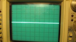
Have you checked the gate signal on a scope?
So I must have done something to the remote... cause now I have the following readings:
KA7500bd
pin1: 6.26
pin 2: 2.521
pin 3: 4.26v
pin 4: 3.567
pin 5: 1.536
pin 6: 3.644
pin 7: 0
pin 8: 13.14
pin 9: 0
pin 10: 0
pin 11: 13.14
pin 12:13.14
pin 13: 4.96
pin 14: 4.96
pin 15: 4.96
pin 16: 0v
Still no ps gate drive signal though...
KA7500bd
pin1: 6.26
pin 2: 2.521
pin 3: 4.26v
pin 4: 3.567
pin 5: 1.536
pin 6: 3.644
pin 7: 0
pin 8: 13.14
pin 9: 0
pin 10: 0
pin 11: 13.14
pin 12:13.14
pin 13: 4.96
pin 14: 4.96
pin 15: 4.96
pin 16: 0v
Still no ps gate drive signal though...
Last edited:
Pin 1 of the KIA7500 is driven from IC2 pin 1 or 7 on the power supply pwm board.
D206 is the protect line from the output card, goes to pin 11 of the power supply pwm board. What voltage do you have on either side of D206?
If you lift D206 it may keep it from protecting, but use caution when doing this. Limit current and watch the current as you power it up.
D206 is the protect line from the output card, goes to pin 11 of the power supply pwm board. What voltage do you have on either side of D206?
If you lift D206 it may keep it from protecting, but use caution when doing this. Limit current and watch the current as you power it up.
Thank you brandes, I'm pretty sure Perry gave me a schematic a lil while ago. I'll have to find where I put it.
I have roughly 2.500 on the cathode side of D206 and it keep falling to 2.450 then jumps back to 2.5 and starts to fall again. I have 0.000v on the anode side.
I'll get more into this after work tonight
I have roughly 2.500 on the cathode side of D206 and it keep falling to 2.450 then jumps back to 2.5 and starts to fall again. I have 0.000v on the anode side.
I'll get more into this after work tonight
Last edited:
I have the following voltages on IC2 (IL393):
Pin 1: 6.62v
Pin 2: 2.473v
Pin 3: 2.53v
Pin 4: 0.000v
Pin 5: 1.025v
Pin 6: 3.23v
Pin 7: 0.116v
Pin 8: 12.67v
There is nothing on any pin of the LM293 (U1) on the output card. There is no voltage on any of the cards pins.
Pin 1: 6.62v
Pin 2: 2.473v
Pin 3: 2.53v
Pin 4: 0.000v
Pin 5: 1.025v
Pin 6: 3.23v
Pin 7: 0.116v
Pin 8: 12.67v
There is nothing on any pin of the LM293 (U1) on the output card. There is no voltage on any of the cards pins.
Last edited:
Q7, 11, 19 and 22 commonly fail on these boards. Do you think that it's possible that one has failed and it's simply a coincidence that it failed when he was testing the speakers?
Why was he popping the speakers? Was he possibly already having trouble with the amplifier.
You stated that the amp was connected but didn't say that it was on so I'm assuming that it was not on. If that's true, the amplifier circuit would not have been connected to the speaker wires because the relay would not have been closed.
I guess anything is possibly when it comes to this stuff Perry. They pop speakers when you run 8ga speaker wire thats all the same color and have multiple coils and speakers to make sure they have the right speaker and proper polarity. Some vehicles are just a wad of wire ends to work with.
I'm not sure if radio (amp) was on or not. He just said it worked in the morning and didn't work after he was done wiring the subs.
I checked Q7, 11, 19 & 22 with my DMM. All pin configurations have high resistance and checking them on the board in diode check they appear fine. There is however no voltage on any pin with power applied (I assume cause of protect).
Can I lift D206 and see what happens? I do have a 50watt 2 ohm resistor to limit current. The amp is still in the case.
This amp is driving me nuts... , lol
, lol
I'm not sure if radio (amp) was on or not. He just said it worked in the morning and didn't work after he was done wiring the subs.
I checked Q7, 11, 19 & 22 with my DMM. All pin configurations have high resistance and checking them on the board in diode check they appear fine. There is however no voltage on any pin with power applied (I assume cause of protect).
Can I lift D206 and see what happens? I do have a 50watt 2 ohm resistor to limit current. The amp is still in the case.
This amp is driving me nuts...
, lolNot sure if it means anything but I noticed as soon as I apply remote the protect light comes on. Then it turns off for a second and the power light flashes and then back to protect. It does this twice before the protect light stays on. So basically it tries 2 twice to turn on. dunno...
One thing I'm not understanding...
The output driver card only has like .003 - .005v on pins 1-1 to 1-7 & 3-1 to 3-7. On pin 2-1 I have 4.24v the same as the cathode on D206 (protection circuit). The other 7 pins 2-2 to 2-8 are 0.000v. Now is the voltage coming from pin 11 of the PS card? or is it going to it? I thought it was in "input" for the comparator on the PS card, so it would have to be outputted from the output card?
What drives the output card? The 12v regulated voltage that I don't have? how is this 4.2v being created? Looks like I have 12.7v up to R4A then after the zenner and diode I have 4.2 at point R29B. Then it goes into the comparator input.
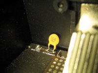
One of the other comparator input is TH1. It has resistance, so I think its fine.
I'm lost...
The output driver card only has like .003 - .005v on pins 1-1 to 1-7 & 3-1 to 3-7. On pin 2-1 I have 4.24v the same as the cathode on D206 (protection circuit). The other 7 pins 2-2 to 2-8 are 0.000v. Now is the voltage coming from pin 11 of the PS card? or is it going to it? I thought it was in "input" for the comparator on the PS card, so it would have to be outputted from the output card?
What drives the output card? The 12v regulated voltage that I don't have? how is this 4.2v being created? Looks like I have 12.7v up to R4A then after the zenner and diode I have 4.2 at point R29B. Then it goes into the comparator input.
One of the other comparator input is TH1. It has resistance, so I think its fine.
I'm lost...
Last edited:
- Status
- This old topic is closed. If you want to reopen this topic, contact a moderator using the "Report Post" button.
- Home
- General Interest
- Car Audio
- AQ 2200