Hello,
I have bought faulty Jl 300/2 audio amp. Amp was repaired an unauthorized person before.
+-53V ok.
-+15V ok. (+-17V)
r513 resistor 3.8V near yellow transformer.
Driver boards led are fine (Green LIGHTS ON). Some driver transistors are hot.
Right channel Q300 FET source joint burning when amp is on. Fets are new and OEM. No short! good solder joints. Gate resistors are fine. Current is very high over 5 amps.. Amp self shut down..
So I decide remove R channel q300 q301 fets and make test again. Current became stable 1,2A. Amp stop switching OFF. I check gate voltage (remote ON) q300 q301 is 0V. So problem is driver board. I take it off driver board and check few first transistors directly from q300/301 gate they are fine... Some driver board transistors are hot..
Left channel gate resistors are fine and voltage is ¬3.5V (REMOTE ON). 0V remote off. I am idiot and kill left channel driver board too . I just touch driver board and amp current became very high again about 4amps, but amp wont switching again... Now left channel fets gate voltage when remote in ON = 0v.
Any Ideas?
THANK YOU!
I have bought faulty Jl 300/2 audio amp. Amp was repaired an unauthorized person before.
+-53V ok.
-+15V ok. (+-17V)
r513 resistor 3.8V near yellow transformer.
Driver boards led are fine (Green LIGHTS ON). Some driver transistors are hot.
Right channel Q300 FET source joint burning when amp is on. Fets are new and OEM. No short! good solder joints. Gate resistors are fine. Current is very high over 5 amps.. Amp self shut down..
So I decide remove R channel q300 q301 fets and make test again. Current became stable 1,2A. Amp stop switching OFF. I check gate voltage (remote ON) q300 q301 is 0V. So problem is driver board. I take it off driver board and check few first transistors directly from q300/301 gate they are fine... Some driver board transistors are hot..
Left channel gate resistors are fine and voltage is ¬3.5V (REMOTE ON). 0V remote off. I am idiot and kill left channel driver board too
. I just touch driver board and amp current became very high again about 4amps, but amp wont switching again... Now left channel fets gate voltage when remote in ON = 0v.Any Ideas?
THANK YOU!
I think I found where is the problem why burning q300 (right channel) source pin.. I check resistance between drain and source (AMP OFF) ir very low about 70ohms. Reverse test meter leads get the same 70ohms value.
I compare q400 resistance (left channel) between drain and source 450ohms. Reverse test meter leads and get continues resistance.
Anybody can help me?
Thank you.
I compare q400 resistance (left channel) between drain and source 450ohms. Reverse test meter leads and get continues resistance.
Anybody can help me?
Thank you.
Are you checking the transistor in the board, checking the pads on the board (transistor out) or the transistor out of the circuit?
Thank you Perry, problem resolved. Just solder few points near wirewound resistors, bad ground connection. Few years unused... Now amp (remote on) current is 1.2A at 14V. Sound clear but green power led wont light. Any ideas? (leds and 4 wires are fine)
What about bias? I have test with digital multimeter 0mV.
I forgot to mention, now I am using IRFB4710 mosfets. Stock IRF540n isn`t best choose.
Cheers
What is the DC voltage across the green LED when the amp is on?
Most of these amps have about 0.004v across the bias points when I check them. I don't know what the factory recommends.
The 4710s will be harder for the driver board to drive. Why not use the original parts? They have proven themselves reliable in these amps.
Most of these amps have about 0.004v across the bias points when I check them. I don't know what the factory recommends.
The 4710s will be harder for the driver board to drive. Why not use the original parts? They have proven themselves reliable in these amps.
Remote ON
U=14.2V
I=1.2A
Green LED = 0.16V (OFF)
BIAS V=0mV (try adjust but nothing happen)
Left channel output fet:
q300/q301 gate U=-15.5 V / Drain U=0V / Source U=-18.4V (Q300/301 gate smd resistors 2x100 Ω)
q304/q305 gate U= 4.8 V / Drain U=V / Source U=0V (Q304/305 gate smd resistors 2x47 Ω)
R channel:
q400/q401 gate U=-13.5 V / Drain U=0V / Source U=-18.4V (Q400/401 gate smd resistors 2x100 Ω)
q404/q405 gate U= 3.2 V / Drain U=18.4V / Source U=0V (Q404/405 gate smd resistors 2x47 Ω)
Driver board R channel:
q14 b= -10.9V k=0V e= -11.5V
q8 b= 3.8V k=53V e=4.9 V
Driver board L channel:
q14 b= -12.5V k=0V e= -13.2V
q8 b= 5.5 k=53V e=4.9 V
where is a problem?
Thank you Perri
Ok Perry, now I can set bias. I set ¬4mV. DC offset is fine. Few problems solved, but power LED wont light.. Later I have found defective 74VCH112 (ground & VCC pins was shorted). Near voltage regulator ground & output +5V pins was shorted too. I get a new 74vhc112 and replace. Now when I try turn ON amp, power led lights up for few 1-2 seconds (current reaches 0.7A) and than amp self shut down. No voltage on test pads nothing. Very strange... Maybe defective shorted 74VCH112 make more troubles? Any ideas?
Thank you
Thank you
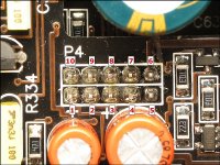
Remote ON
Pin 1-10
1 (0V)
2 (0V)
3 (14.3V)
4 (0V)
5 (14,3V)
6 (14.3V)
7 (14,3V)
8 (0,3V)
9 (0,03V) (14.3V only 3-5s option1)
10 (0V)
Let me explain:
B- (ground) is always connected
OPTION 1
If I connect B+ and remote in the same time, power led comes for 3-5 s current reach 0.5 A and than AMP switch OFF.
OPTION 2
If I connect B+ and later remote nothing happens. Green led wont light at all.
So I always should wait about 10 seconds (and repeat option 1).
- Status
- This old topic is closed. If you want to reopen this topic, contact a moderator using the "Report Post" button.
- Home
- General Interest
- Car Audio
- Jl audio 300/2 please help!