Do you mean that they have 45v across them if you place one probe on each terminal of the resistor?
Did the rail voltage go away on the bridging wires?
The rail voltage has left the orange and white wires but remains at the brown and grey wires.
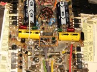
I have rail across that resistor and thats why its burning but I dont know why?
That resistor is connected to the D40D8 and the single MPSA56 that drives that bank. I lifted the 3 fets and removed the 3 A06's in that group of fets.
It has to be either the D40D8 or that single MPSA56 making rail across?
Last edited:
Please read post #11 first.
I tested the pads of the removed D40D8 and found that I had voltage of 14.50 on the center pad and should not have, comparing to the other drivers in circuit.
I traced it back through the circuit and its fed by some small zenners which also had the voltage of 14.50 on both pads and should not have comparing to others in the circuit.
I followed it back a little further to find pin 7 from the LM833 feeds all of that. Pin 7 had the same voltage on it which was 14.50 vdc.
Pin 6 also had 9.50 vdc on it. I compared it to the other op-amp in the channels without the DC and the only pins that had any voltage to speak of were the supply pins.
I think the op-amp failing caused the rail voltage across the resistor and blew the drivers in the orange square you posted a pic of.
I think when I replace the op-amp the rail will be gone on the remainig channels, the resistor will no longer have rail across it, the drivers will be fine and the amp will work.
What do you think?
This is inside the feedback loop. If any component is defective or missing, the voltages could swing to the extremes as the circuit tries to correct for the offset. If the resistor has 40+v across it, the outputs are likely shorted. The gates cannot withstand that much drive voltage.
In these old amps, you'll find a lot of leaky transistors and diodes that are difficult to find without removing them.
In these old amps, you'll find a lot of leaky transistors and diodes that are difficult to find without removing them.
OK when I removed the op-amp it fell apart and was totally cooked inside.
I will probably sub IRF540 and IRF9540 in this amp, do you see any issues with that? Is there anything else besides all the A56 and A06 drivers I should replace?
My op-amps will be here Monday, I want to get a head start.
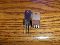
The D40D8 and D41D8 drivers in the amp right now are much larger than the TO-202 package ones I have in stock. What I meant to say is the ones in the amp are similiar in size to a TO-220, thats why I was wondering if the smaller ones I had would work or if they are the same, just smaller because they are newer?
I will probably sub IRF540 and IRF9540 in this amp, do you see any issues with that? Is there anything else besides all the A56 and A06 drivers I should replace?
My op-amps will be here Monday, I want to get a head start.
The D40D8 and D41D8 drivers in the amp right now are much larger than the TO-202 package ones I have in stock. What I meant to say is the ones in the amp are similiar in size to a TO-220, thats why I was wondering if the smaller ones I had would work or if they are the same, just smaller because they are newer?
- Status
- This old topic is closed. If you want to reopen this topic, contact a moderator using the "Report Post" button.
- Home
- General Interest
- Car Audio
- Rockford Fosgate Power 650