Q7, 11, 19 and 22 commonly fail on these boards.
AG and DK are the markings for the part number. I've never seen these fail.
2SA1797 and 2SC4672
Could Q7,11,19,22 being shorted cause outputs to fail?
Could Q18 and Q14 being shorted cause outputs to fail?
Q7 had a burn spot on it, Q14 had a burn spot on it, so I replaced Q7, Q11, Q19, Q22, Q18, Q14.
When I installed the driver board and powered the amp Q5, Q6, Q9, Q12 all went up in smoke.
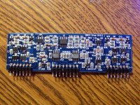
From left to right, under Q12 pin 1 on the driver board was broken and I did not catch it. Maybe this is why The drivers went poof?
Now I have to order parts from Mouser.
I dont understand. I am replacing all the 640 n's while I am waiting for parts.
I am hoping the driver board has caused the issues in this amp.
When I installed the driver board and powered the amp Q5, Q6, Q9, Q12 all went up in smoke.
From left to right, under Q12 pin 1 on the driver board was broken and I did not catch it. Maybe this is why The drivers went poof?
Now I have to order parts from Mouser.
I dont understand. I am replacing all the 640 n's while I am waiting for parts.
I am hoping the driver board has caused the issues in this amp.
I would suspect that they were damaged when the outputs failed or there was a solder bridge between solder pads either at the driver board or at the outputs (less likely).
Check for solder bridges on the plastic header for the driver board (between the plastic and the main board).
Check for solder bridges on the plastic header for the driver board (between the plastic and the main board).
Please read post #11 first.
I replaced all the drivers for the one side of the audio board, Q12,Q6,Q9,Q5.
I powered the amp through a current limiter and it powered up fine.
I have a quick question. I have taken some measurements from the pads of the IRF640N's before installing them or full powering the amp.
Gate: -25vdc
Drain: +26vdc
Sorce: -27vdc
Is this correct? Why is there + voltage on the drain of the "N" channel fets?
None of the "P" channel fets have - voltage on their drains and they are all installed, just has me wondering???
I also have +26.50 vdc on the output terminals and the amp is not in protect???
I dont think the driver board could take another failure, just want to be sure thats right before I power the amp with the fets installed and smoke 12 outputs and more drivers.
Last edited:
#11:
I'm not sure what those are for, If the collector of Q4 goes to a 4.7 ohm resistor and then to a diode then to the first pin of the middle connector, it's likely for the protection circuit.
#12:
You should not have any DC voltage on the drains of any of the outputs with the driver board out of the circuit. If the driver board is in the circuit, it's difficult to say what voltage you should have because half of the output transistors are out of the circuit.
I installed all of the IRF640N's and powered the amp through a limiter.
It still has the +26.50 vdc on the drains of the "N" channel fets but looking at the board all of the drains are connected together from all the output fets so I guess this would be ok.
It is not OK that I have +26.50 vdc on the output terminals though.
The amp is not in protect and has +26.50 vdc on the + output terminals. I am going to have to assume that it would be full rail if the limiter was not in place?
What is letting rail reach the output terminals?
None of the IRF9640 measure shorted in the circuit but I guess that does not mean anything? I am kinda leaning toward another component on the driver board??
What do you think?
- Status
- This old topic is closed. If you want to reopen this topic, contact a moderator using the "Report Post" button.
- Home
- General Interest
- Car Audio
- Hifonics audio driver board