Hi Guys, Audio noob here  but pretty good with a soldering iron..
I am actually trying to add a set of tweeters to my car, you see I own a bmw e36 318is which came with speakers on the door cards, I recently replaced the door cards because of sagging door inserts (a common issue with these cars) and the new door cards have tweeters installed with speakers.
Anyway there aren't any connectors on my car to connect these tweeters so long story short I need some help connecting them if possible.
Both the speaker and tweeter seem to be 8 ohms, so I was told to add a capacitor and a 4ohms resistor to the tweeters..I was also told this may not be safe for my cd player? I got a decent sony cd player.
I dont know, I do have some caps at home so if you could tell me how to make it work I could give it a go...
Here are some pics,
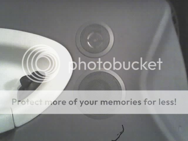

the speaker


and the tweeter

but pretty good with a soldering iron.. I am actually trying to add a set of tweeters to my car, you see I own a bmw e36 318is which came with speakers on the door cards, I recently replaced the door cards because of sagging door inserts (a common issue with these cars) and the new door cards have tweeters installed with speakers.
Anyway there aren't any connectors on my car to connect these tweeters so long story short I need some help connecting them if possible.
Both the speaker and tweeter seem to be 8 ohms, so I was told to add a capacitor and a 4ohms resistor to the tweeters..I was also told this may not be safe for my cd player? I got a decent sony cd player.
I dont know, I do have some caps at home so if you could tell me how to make it work I could give it a go...
Here are some pics,
the speaker
and the tweeter

Okay So I solder 1x 4.7uF capacitor to the negitive and positive terminal of the tweeter. then I can connect them to the wire feeding the midrange speaker, I was also told to install a 4ohms resistor on the positive wire in order to correct the impedance an bring it all back to 8ohms? is that correct? Also Do I need a non polarized cap? how do I tell if my cap is polarized or non polarized ?
So thats all I need to do? nothing to worry about it causing any damage or something to my cd player?
I was given this instructions by someone, please have a look..
Thank you for your time and help.
So thats all I need to do? nothing to worry about it causing any damage or something to my cd player?
I was given this instructions by someone, please have a look..
Wire the capacitor across the positive and negative terminals on the tweet
Cut the wires that go to the original speaker, strip back
So now you have a wire that goes to the car, one to the original speaker and one to the tweet and obviously the same for the negative
solder the resistor to the positive wire from the car then solder the positive tweet wire and speaker wire to the other side of the resistor
Solder the negative tweet wire and original speaker wire to the negative wire
Heat shrink over them all job done
Thank you for your time and help.
Negative OR positive, not both. If you solder it across the positive and negative terminals, it will shunt all of the high frequencies away from the tweeter.
I don't think you need the resistor. Adding it will increase the impedance slightly but with a 4.7uF capacitor, the tweeter will only load the amp significantly above 5000Hz. It's not likely to be a problem unless the amplifier driving it is very fragile.
You need a non-polarized capacitor.
There are no guarantees that modifying the system won't cause any damage to the CD player. There are always risks involved and something as simple as letting a wire touch to ground for a fraction of a second could be enough to cause extensive damage.
Okay Thanks, So to speak, Whats the difference between a regular capacitor and a non polarized capacitor? How do I know if its the non polarized capacitor? I mean distinguish the difference? is there any electronics I might be able to salvage some from or I get them from the store.
I made this diagram for wiring tweeters to the e36 bmw speakers...is that about right for the crossover? I am using a 3.9omh resistor on each door along a 4.7uF non polarized capacitor.so overall I am thinking I should be safe with this, I mean I am good with the iron and heatshrink cables and everything..let me know what you think..

I made this diagram for wiring tweeters to the e36 bmw speakers...is that about right for the crossover? I am using a 3.9omh resistor on each door along a 4.7uF non polarized capacitor.so overall I am thinking I should be safe with this, I mean I am good with the iron and heatshrink cables and everything..let me know what you think..
Non polarised means it can tolerate DC voltage of either polarity across it up to its rated voltage. Normal electrolytic caps are polarised and and must be fitted the correct way around if any DC is present.
You can make a non or bi-polar cap by connecting two electros in series. For 4.7uf you would use two 10uf caps to give a total of 5uf for the series cap. Connect either plus to plus or minus to minus for the series connection. It doesn't matter which.
Edit... the resistor for the tweeter would go in series with just the tweeter, not the main speaker as well.
Normal (polarized) capacitors are designed to work with DC only. Audio is AC so you need to use non-polarized capacitors.
The diagram is correct. You should know that this will slightly decrease the output of the midrange speaker. The resistor may also dissipate a great deal of heat (depending on how loud you play the system). It could get hot enough to melt plastic. I'd recommend a 5 watt resistor as a minimum.
The diagram is correct. You should know that this will slightly decrease the output of the midrange speaker. The resistor may also dissipate a great deal of heat (depending on how loud you play the system). It could get hot enough to melt plastic. I'd recommend a 5 watt resistor as a minimum.
Okay I see, So I will put the resistor after the main speaker and somewhere before the tweeter or it non polarized cap? I dont know why I am using a resistor but it will get hot and lower output of the midrange speaker? nof if placed before the tweeter right? I was suggested I use a 5 Watt 4 ohms resistor by someone else in another forum who said since both speakers are 8 ohms I need to use a resistor on each side to bring down the impedance level or that its better overall or something like that. How correct is that?
So you guys are telling me I can connect 2 regular 10uF caps and mimic a 4.7uF cap? how is that done exactly, any guides or diagrams?
Thank you for the help, I really appreciate it.
So you guys are telling me I can connect 2 regular 10uF caps and mimic a 4.7uF cap? how is that done exactly, any guides or diagrams?
Thank you for the help, I really appreciate it.
forgot to ask one more thing...the capacitor, does it matter what voltage its rated at? You know some of the ones I have are ratted at 6.3V and some around 10V some 16V.
Also to clearly, When you say it is 4.7uF do you guys actually mean 470uF. So in that case I would grab two 1000uF capacitors, and solider their positive legs together which will make it around 470 - 500uF. right?
Also to clearly, When you say it is 4.7uF do you guys actually mean 470uF. So in that case I would grab two 1000uF capacitors, and solider their positive legs together which will make it around 470 - 500uF. right?
So you guys are telling me I can connect 2 regular 10uF caps and mimic a 4.7uF cap? how is that done exactly, any guides or diagrams?
As in post #9
4.7 uf sounds in the right ballpark value wise... give or take depending on exact specs. Its certainly not 470uf.
The voltage of the cap needs to be able to stand the peak voltage the amp puts out. The lower the frequency the more voltage the cap "drops".
If this is a Sony CD player (I missed the make in the first post), the resistor is definitely not required if you are driving only the mid and the tweeter on that channel of the head unit. If you look up the specs for the head unit, you'll likely find that it's designed to drive a 4 ohm load.
You should be able to find a 4.7uf mylar/film or non-polarized electrolytic capacitor at virtually car audio shop.
The capacitor will never see more than 15v if it's driven from the head unit.
You should be able to find a 4.7uf mylar/film or non-polarized electrolytic capacitor at virtually car audio shop.
The capacitor will never see more than 15v if it's driven from the head unit.
If this is a Sony CD player (I missed the make in the first post), the resistor is definitely not required if you are driving only the mid and the tweeter on that channel of the head unit. If you look up the specs for the head unit, you'll likely find that it's designed to drive a 4 ohm load.
You should be able to find a 4.7uf mylar/film or non-polarized electrolytic capacitor at virtually car audio shop.
The capacitor will never see more than 15v if it's driven from the head unit.
Okay Thanks Perry,
Its a Sony CDX-F7710, So I guess I will just skip the resistor altogether? And just hot glue two 10uF caps to the side of per tweeter (with their positive legs connected to each other by a wire) and negative leg connected to the Positive speaker wire and a wire leading to the positive terminal on the speaker. To mimic a non polarized cap? am I right?
I have found some regular 50V 10uF Caps in my tool box.
Let me know guys...thanks
What is it that was not previously covered that you need to know?
Just wanted to double check Perry. Wanted to tell you my CD players Model number and caps I am about to use, You know I am new to this so just wanted you to know and confirm thats all. You know just incaase I had something wrong. better be safe then sorry.
Thanks for your time
- Status
- This old topic is closed. If you want to reopen this topic, contact a moderator using the "Report Post" button.
- Home
- General Interest
- Car Audio
- Need Help Adding Tweeters to Speakers